
Lens module socket
a technology of lens module and socket, which is applied in the direction of mountings, television systems, instruments, etc., can solve the problems of difficulty in meeting the compact size requirement of electronic products, and achieve the effect of reducing the total height of the assembly
Patent Information
- Authority / Receiving Office
- US · United States
- Patent Type
- Applications(United States)
- Current Assignee / Owner
- Publication Date
- 2011-07-28
- Estimated Expiration
- Not applicable · inactive patent
Smart Images
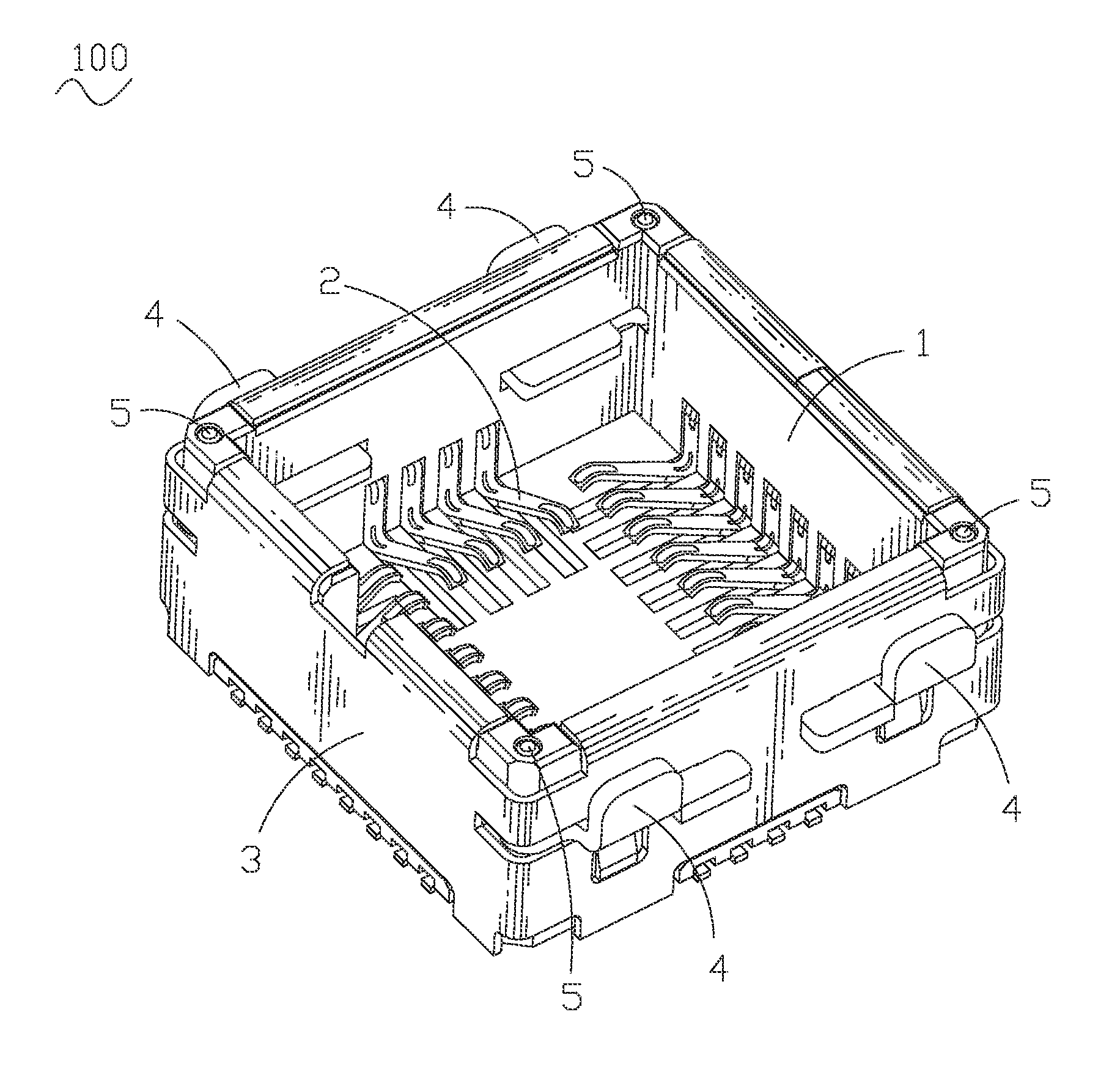
Figure 1 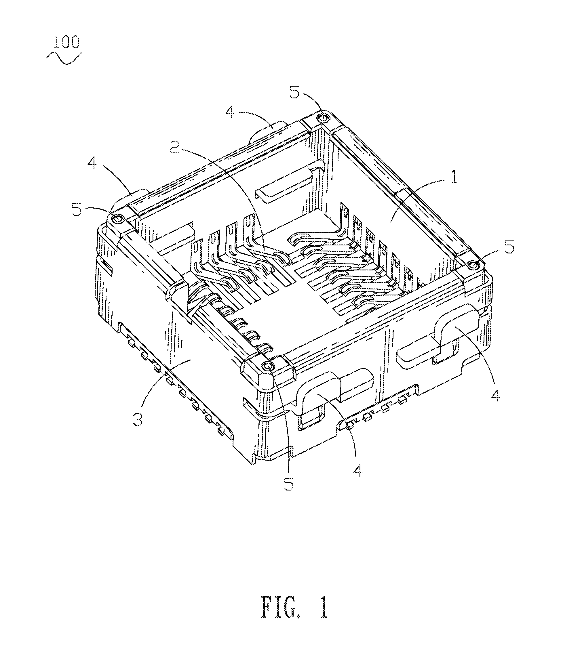
Figure 2 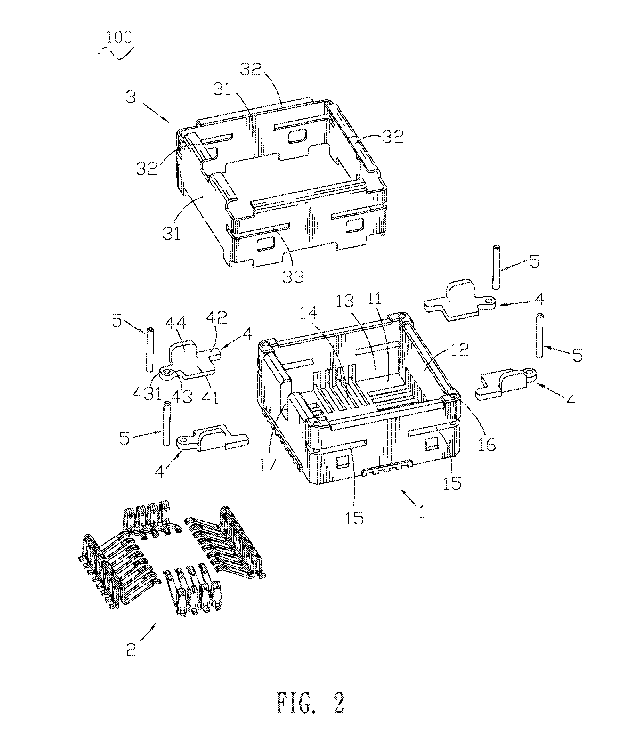
Figure 3
Abstract
Description
BACKGROUND OF THE INVENTION1. Field of the InventionThe present invention relates to a lens module socket, and more particularly to a lens module socket for receiving a lens module to reduce the total height of the assembly thereof.2. The Related ArtBecause of the development of wireless communication and the rapid revolution in high technology, portable electronic products, such as mobile phones, PDAs and notebook computers, are assembled with different electronic additional-modules such as lens modules for taking pictures and satisfying desires of consumers. Correspondingly, the lens module sockets spring up for the lens modules.In general, a lens module socket includes an insulating housing defining a receiving chamber therein for receiving a lens module, a plurality of conductive terminals received in the insulating housing, and a shielding shell encircling the insulating housing. The insulating housing has a bottom base and four side walls extended upwardly from the bottom base...
Examples
Embodiment Construction
With reference to FIG. 1 and FIG. 2, a lens module socket 100 according to the present invention includes an insulating housing 1, a plurality of conductive terminals 2 received in the insulating housing 1, a shielding shell 3 encircling the insulating housing 1, and a plurality rotatable latches 4 pivotally assembled to the insulating housing 1 by a plurality of shaft pins 5.
The insulating housing 1 has a flat bottom base 11 and four side walls 12 respectively extended upwardly from four sides of the bottom base 11 to surround a receiving chamber 13 therebetween. The bottom base 11 defines a plurality of terminal grooves 14 extended to the side walls 12 for receiving a plurality of conductive terminals 2. The insulating housing 1 defines a plurality of slits 15 substantially parallel to the bottom base 11 and penetrating through two opposite side walls 12 to communicate with the receiving chamber 13. Furthermore, an inside of one end of each slit 15 is blocked by an adjacent side w...