
Method for Establishing an Inter-Domain Path that Satisfies Wavelength Continuity Constraint
a technology of inter-domain paths and wavelength continuity constraints, applied in the field of communication technology, can solve the problems of increasing the cost of wavelength converters, reducing the use of wavelength converters, and difficulty in establishing an inter-domain path that satisfies wavelength continuity constraints in multi-domain networks, so as to improve resource utilization, reduce computation delays, and save time in configuring wavelength
Patent Information
- Authority / Receiving Office
- US · United States
- Patent Type
- Applications(United States)
- Current Assignee / Owner
- Publication Date
- 2012-12-06
- Estimated Expiration
- Not applicable · inactive patent
Smart Images
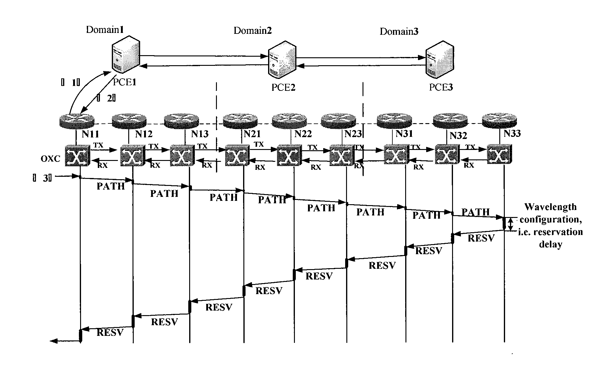
Figure 1 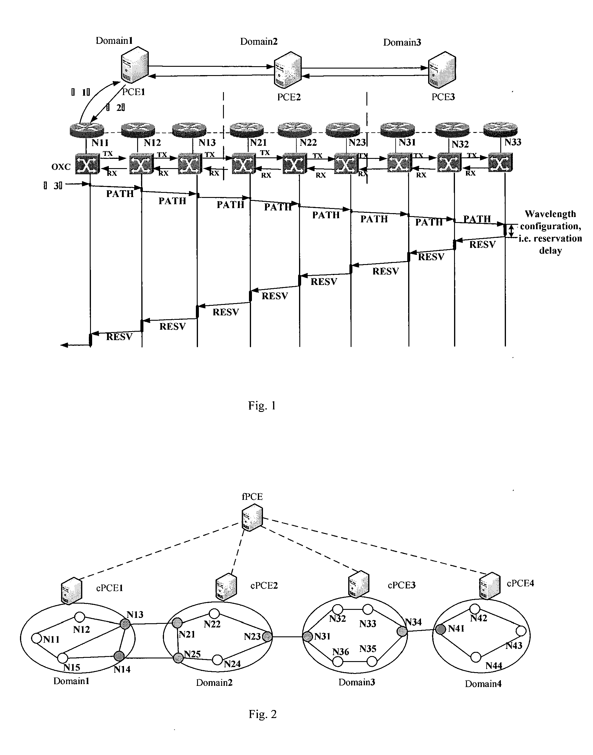
Figure 2 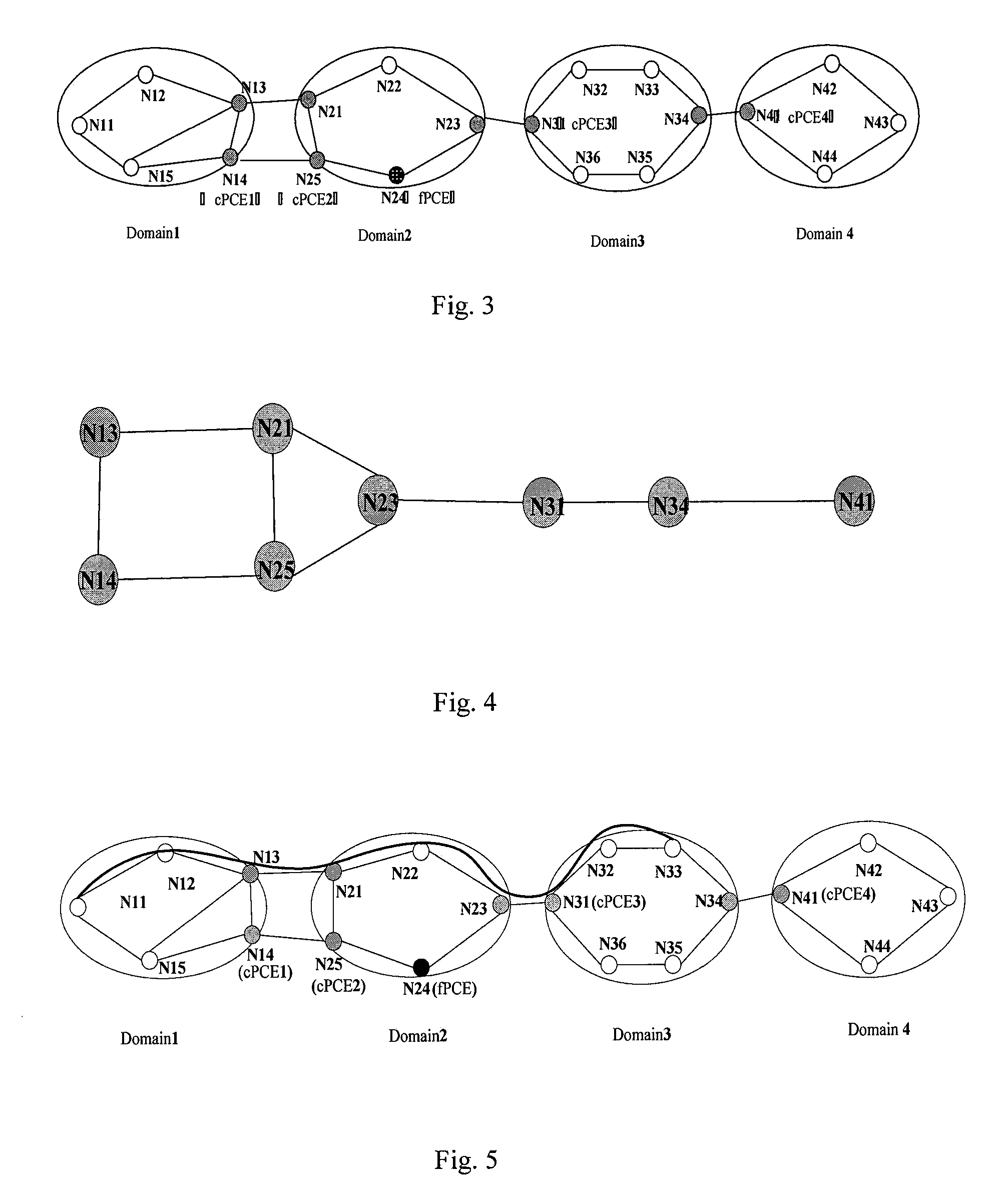
Figure 3
Abstract
Description
CROSS REFERENCED TO RELATED APPLICATIONS
[0001] This application claims priority under the Paris Convention to Chinese Patent Application No. 201110146505.5, Filed Jun. 1, 2011, the entirety of which is hereby, incorporated by reference for all purposes as if fully set forth herein.FIELD OF THE INVENTION
[0002] The present invention relates to the field of communication technology, more particularly to a method for establishing an hierarchical PCE-based inter-domain path that satisfies wavelength continuity constraint.BACKGROUND OF THE INVENTION
[0003] With the development of network technology, the network services grow explosively. And wavelength division multiplexing (WDM) can satisfy the ever-increasing bandwidth demands, so it will be the core technology for future all optical networks undoubtedly.
[0004] In WDM based wavelength switch optical networks, the wavelength converters are expensive, so decreasing the use of wavelength converters is necessary. When there are few wavelength co...
Examples
embodiment 1
[0039]In one embodiment, as shown in FIG. 2˜FIG. 4, the present invention utilizes hierarchical PCE architecture.
[0040]FIG. 2 is a schematic diagram of the logically hierarchical PCE topology architecture. As shown in FIG. 2, the fPCE is located at up layer, coordinating all cPCEs. The cPCEs are placed at lower layer, responsible for path computing and wavelength checking on path segments.
[0041]FIG. 3 is a schematic diagram of the physically hierarchical PCE topology architecture corresponding to FIG. 2. Node N13, N14; N21, N25, N23; N31, N34; N41 are border nodes of Domain1˜4. The cPCEs are placed at border node N14, N25, N31, N41 respectively. The fPCE can be placed at node which locates in middle domain or isolated as an independent device. In this embodiment, the fPCE is placed at node N24 in Domain2. The fPCE maintains a traffic engineering database (TED) which stores a virtual topology architecture comprised by all the border nodes of the domains. It is used to compute abstrac...
embodiment 2
[0055]FIG. 8 is another schematic diagram of the physically hierarchical PCE topology architecture corresponding to FIG. 2 according to one embodiment of the present invention. There are two connection ways between the fPCE and the cPCEs. The first one is indirect connection, in which the fPCE and the cPCEs are placed at some nodes in the network, and they communicates through middle node between them, as shown in FIG. 3 in embodiment 1. The second one is direct connection. The fPCE is isolated from the nodes as an independent device. It connects with each cPCE directly, as shown in FIG. 8. The difference between embodiment 2 and embodiment 1 is the position that the fPCE is placed at. The ways of inter-domain path establishment are the same.