
Lock pin for variable valve timing mechanism
Patent Information
- Authority / Receiving Office
- US · United States
- Current Assignee / Owner
- Publication Date
- 2013-05-23
- Estimated Expiration
- Not applicable · inactive patent
Smart Images
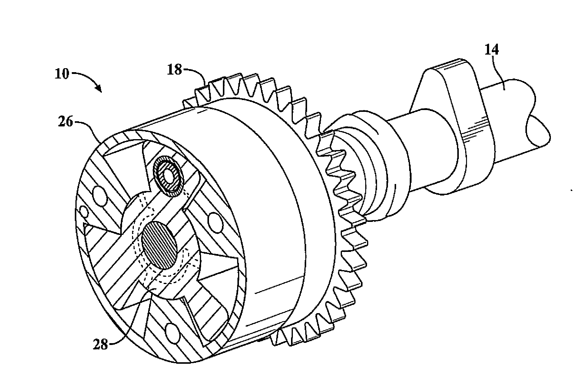
Figure 1 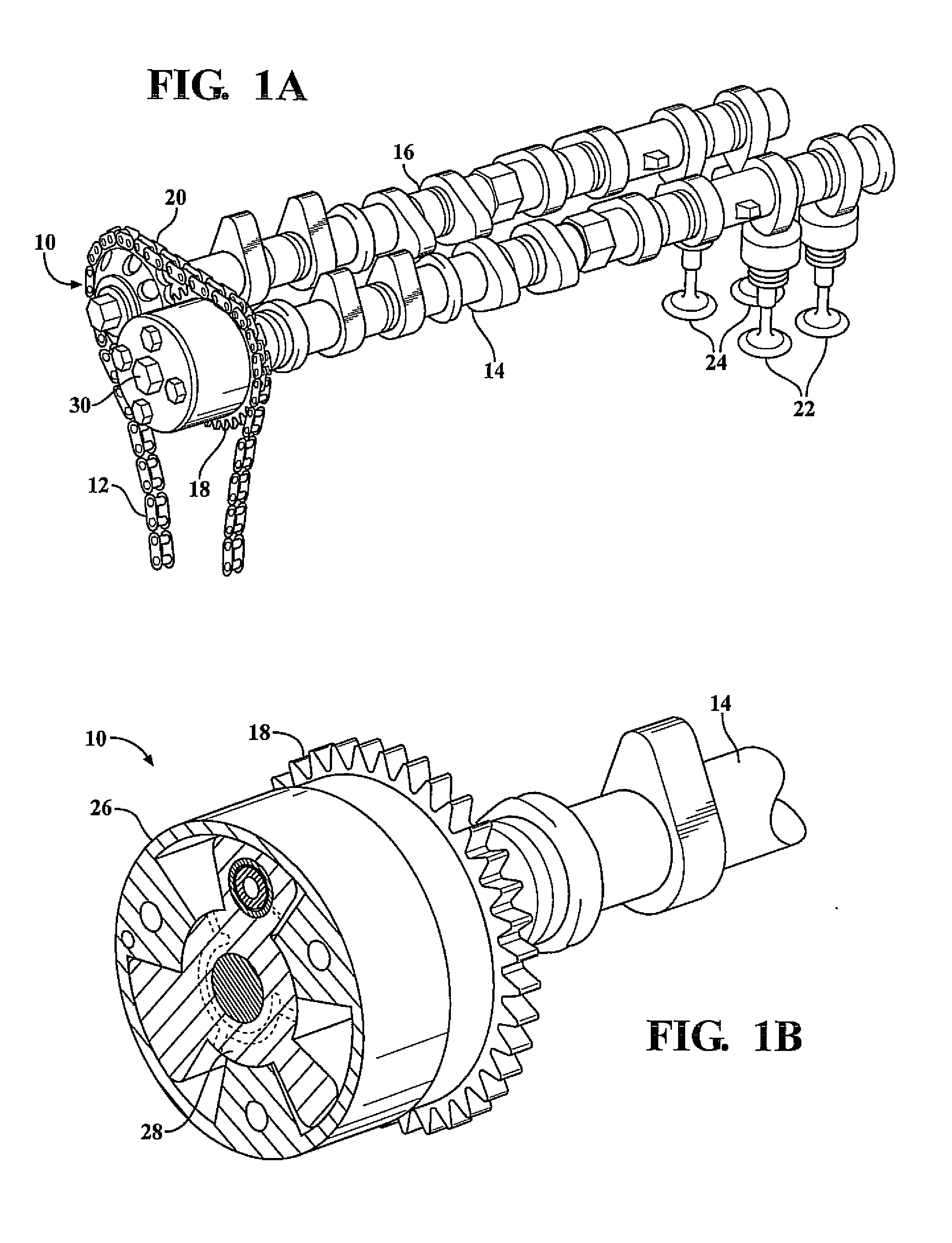
Figure 2 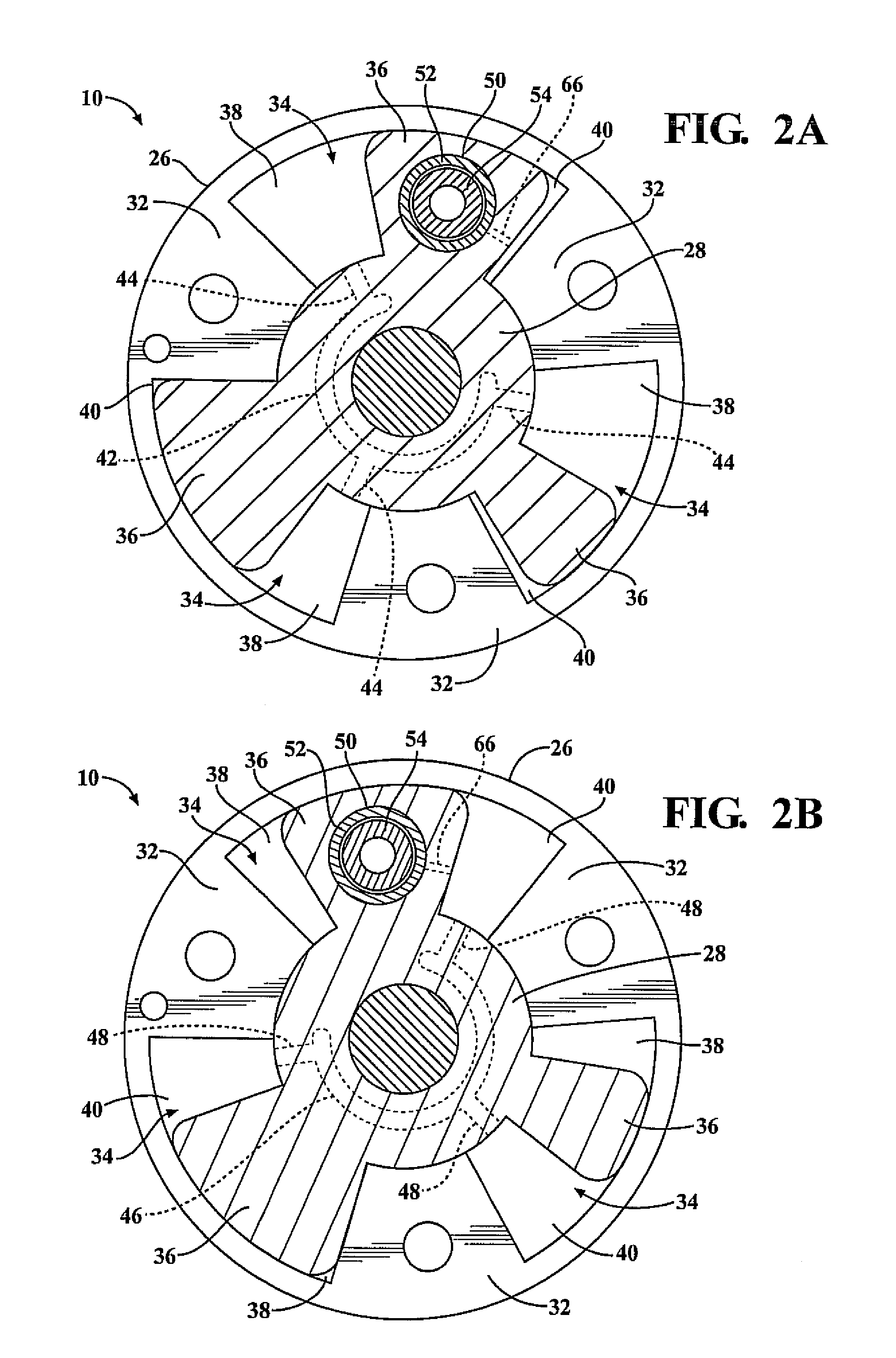
Figure 3
Abstract
Description
FIELD OF THE INVENTION
[0001] The present invention is directed to a variable valve timing mechanism. More particularly, a variable valve timing mechanism having a lock pin that includes an insertion section having a segmented spherical shape.BACKGROUND OF THE INVENTION
[0002] Most modern automotive vehicles include a variable valve timing mechanism in order to vary the opening and closing valve times of the exhaust and intake valves. Typically variable valve timing mechanisms include a lock pin that locks the variable valve timing mechanism during a shutdown of the internal combustion engine in preparation for the engine's next start. However, if the lock pin fails to properly engaged or disengage, the variable valve timing mechanism produces increased noise and vibrations during shutdown and startup procedures. The increase in noise and vibrations result in a decrease in customer satisfaction and affects the perception of quality of the engine.
[0003] With reference to FIGS. 5A-5C, a pr...
Examples
Embodiment Construction
[0025]The present invention has utility as a variable valve timing mechanism, for an internal combustion engine, that provides a lock pin that reliably engages and disengages with a lock bore to prohibit or allow relative rotation between a rotor and housing. By providing the lock pin with an insertion section having a segmented spherical shape, the lock pin can be easily inserted within a lock bore due to the smaller diameter the distal end of the insertion section with respect to the lock bore, and easily disengaged from the lock bore while avoiding a jamming effect between the lock pin and the lock bore due to the nonlinear.
[0026]With reference to FIG. 1, a variable valve timing mechanism for an internal combustion engine is generally illustrated at 10. The engine includes a crankshaft in which the reciprocating motion of pistons of the engine is converted into a rotary motion of the crankshaft. A timing chain 12 transmits the driving force from the crankshaft to an intake side c...