
Self-oscillating loop based piezoelectric power converter
a piezoelectric power converter and self-oscillating technology, applied in the direction of electric variable regulation, process and machine control, instruments, etc., can solve the problems of inductor occupying space, significant maintenance challenge, and particularly pronounced problems
Patent Information
- Authority / Receiving Office
- US · United States
- Current Assignee / Owner
- Publication Date
- 2014-11-13
- Estimated Expiration
- Not applicable · inactive patent
Smart Images
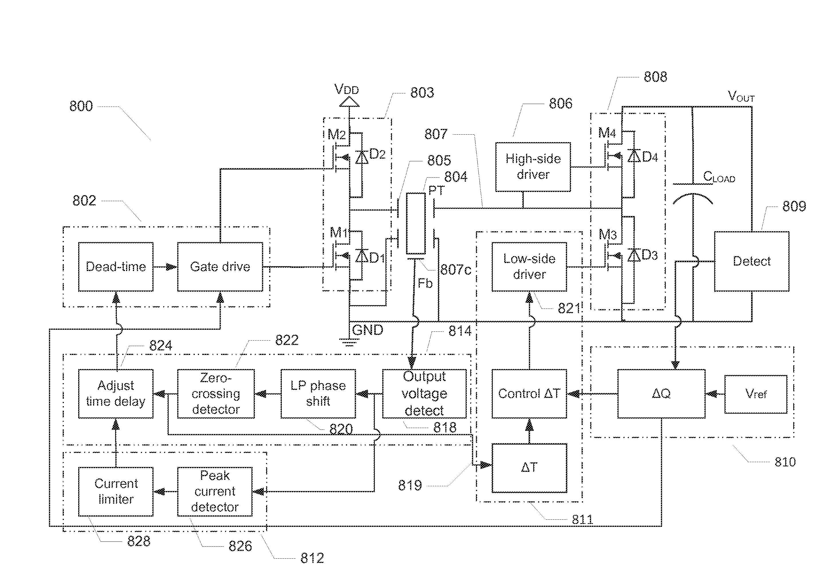
Figure 1 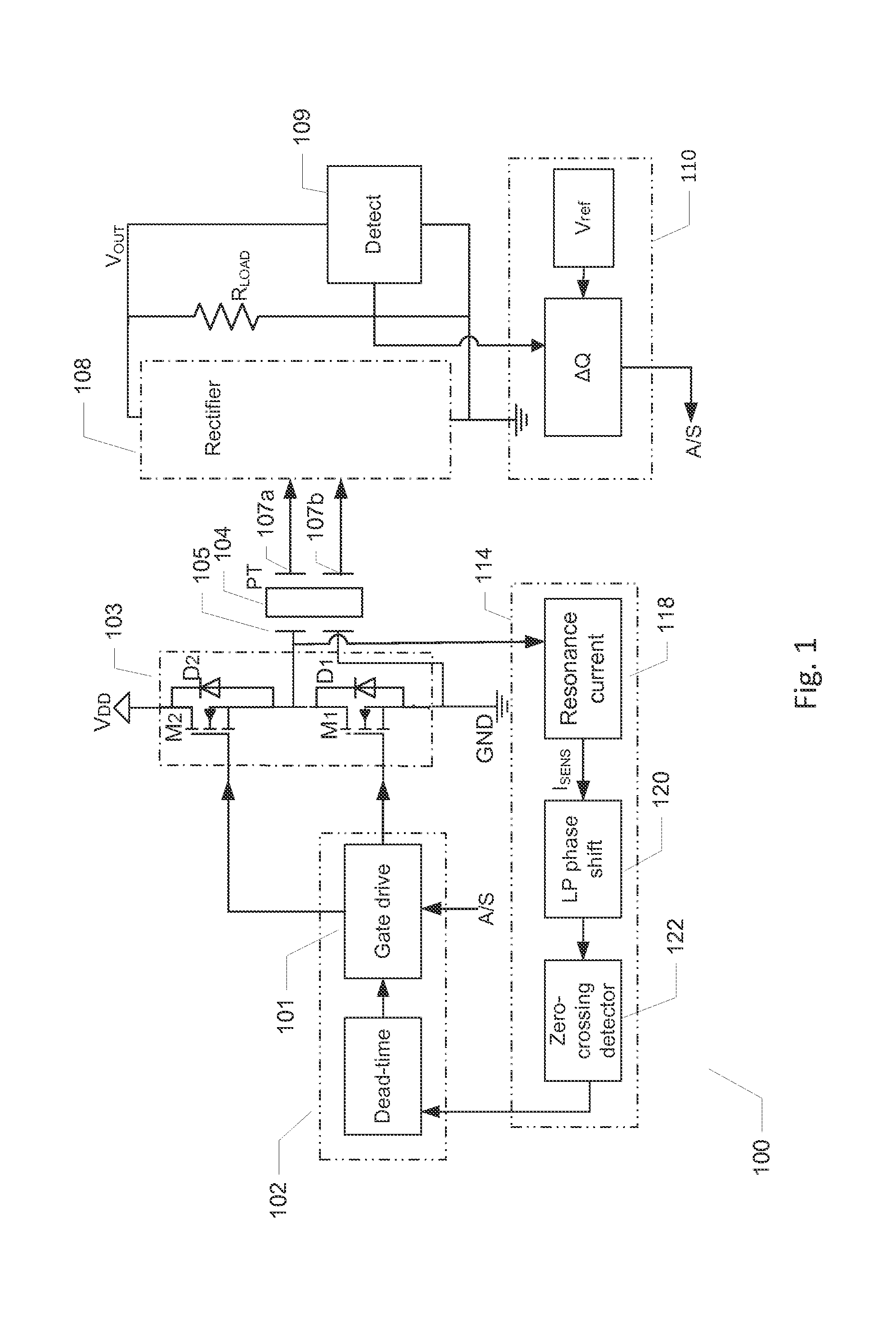
Figure 2 
Figure 3
Abstract
Description
[0001] The present invention relates to a piezoelectric power converter comprising an input driver electrically coupled directly to an input or primary electrode of the piezoelectric transformer without any intervening series or parallel inductor. A feedback loop is operatively coupled between an output voltage of the piezoelectric transformer and the input driver to provide a self-oscillation loop around a primary section of the piezoelectric transformer oscillating at an excitation frequency. Electrical characteristics of the feedback loop are configured to set the excitation frequency of the self-oscillation loop within a zero-voltage-switching (ZVS) operation range of the piezoelectric transformer.BACKGROUND OF THE INVENTION
[0002] Piezoelectric transformer based power converters have good potential to substitute traditional magnetics based power converters in numerous voltage or power converting applications such as AC / AC, AC / DC, DC / AC and DC / DC power converter applications. Piezo...
Examples
first embodiment
[0049]FIG. 1 shows a schematic block diagram of a piezoelectric power converter 100 in accordance with the invention. The bi-directional piezoelectric power converter 100 comprises a piezoelectric transformer, PT, 104. The piezoelectric transformer, PT, 104 has a first input electrode 105 electrically coupled to an input or primary section of the piezoelectric transformer 104, coupled to the input driver 103 of the piezoelectric power converter and a second input electrode connected to ground, GND. A first output electrode 107a and second output electrode 107b of the piezoelectric transformer 104 are electrically coupled to secondary or output section of the piezoelectric transformer 104 to provide a differential transformer output voltage or signal to a rectification circuit 108. The rectification circuit 108 may comprise a half or full wave rectifier and an output capacitor to provide smoothed DC voltage at the output node or terminal VOUT.
[0050]The piezoelectric power converter 1...
third embodiment
[0063]FIG. 7 illustrates a simplified electrical equivalent diagram inside dotted box 604 of the piezoelectric transformer 604 of the piezoelectric power converter 600 in accordance with the invention. The simplified electrical equivalent diagram comprises a pair of separate secondary windings where the load is coupled to the upper secondary winding which also provides the positive DC output voltage VOUT. The rectifier has been left out of the diagram for simplicity. The lower secondary winding corresponds to the separate feedback output electrode 607c and provides a feedback output signal VFB to the output voltage detection circuit 618. As illustrated on the drawing, the lower secondary winding is galvanically isolated from the upper secondary winding and therefore not used to supply power to the load. Hence, the volume of the output section occupied by the separate feedback output electrode 607c can be much smaller than the volume of the output section(s) enclosing the output elec...