
Liquid crystal display device
Patent Information
- Authority / Receiving Office
- US · United States
- Current Assignee / Owner
- Publication Date
- 2015-06-11
Smart Images
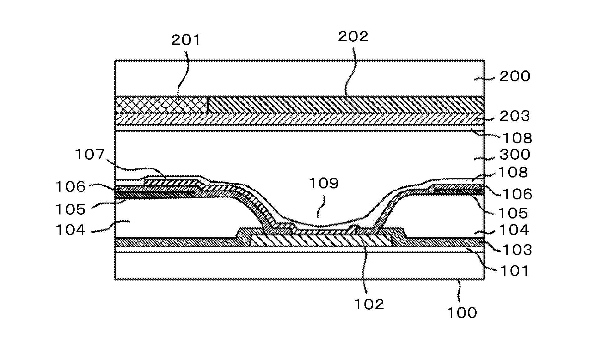
Figure 1 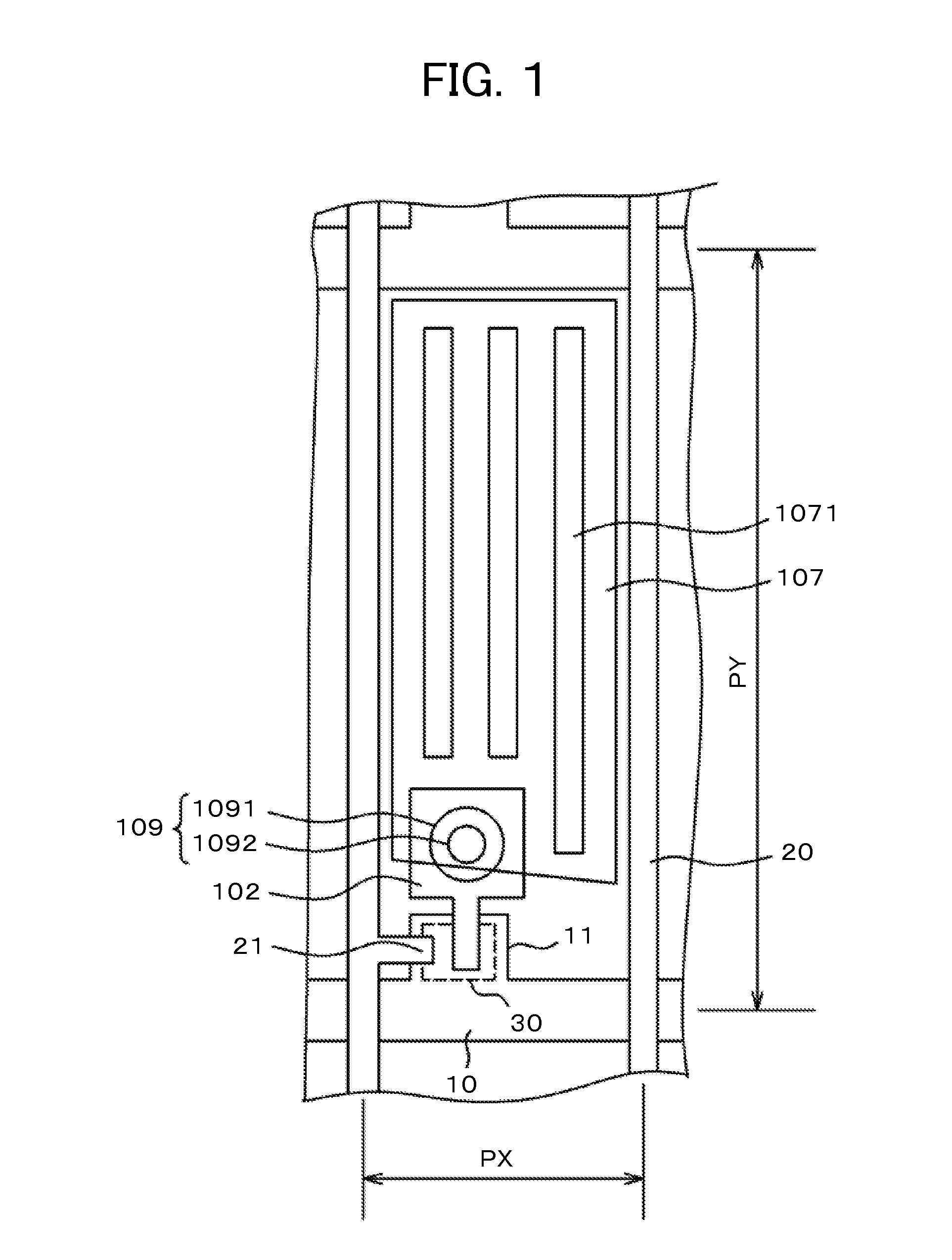
Figure 2 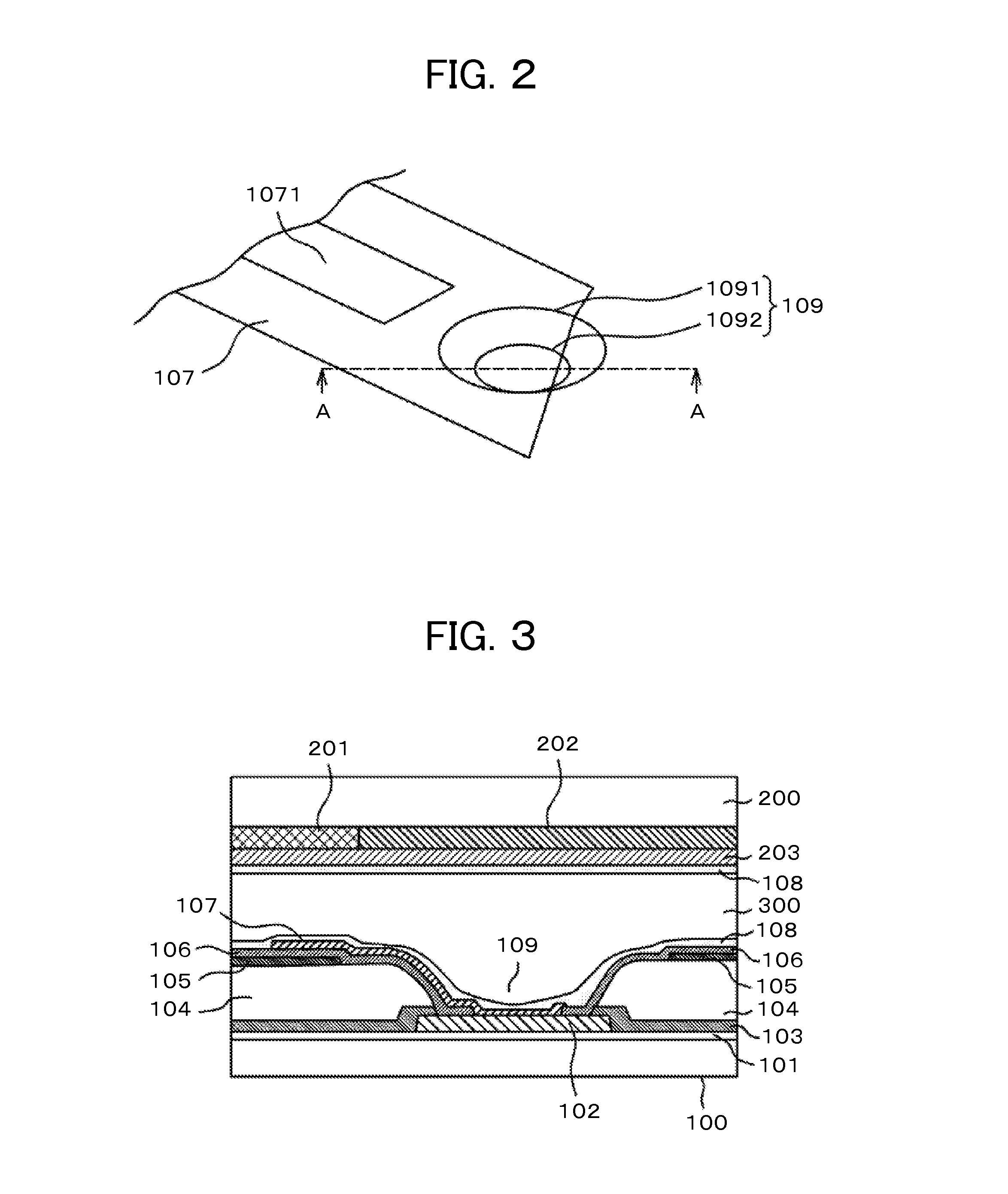
Figure 3
Abstract
Description
CLAIM OF PRIORITY
[0001] The present application claims priority from Japanese Patent Application JP 2013-254205 filed on Dec. 9, 2013, the content of which is hereby incorporated by reference into this application.BACKGROUND OF THE INVENTION
[0002] 1. Field of the Invention
[0003] The present invention relates to a display device. The invention more particularly relates to a liquid crystal display device in which reduction in transmissivity is small even in a case where the screen is a high-definition screen, the liquid crystal display device having few pixel defects in the high-definition screen.
[0004] 2. Description of the Related Art
[0005] In a liquid crystal display device, a thin film transistor (TFT) substrate in which pixels each including a pixel electrode, a TFT, and the like are formed like a matrix, a counter substrate facing the TFT substrate and having color filters formed at positions in facing relation to the pixel electrodes on the TFT substrate are arranged, and liquid cry...
Examples
first embodiment
[0047]FIG. 1 is a plan view of a pixel in a TFT substrate of a liquid crystal display device to which the present invention is applied. FIG. 1 illustrates an example of an IPS liquid crystal display device. In FIG. 1, scanning lines 10 extend in a lateral direction and are arranged in a longitudinal direction at a predetermined pitch PY. Video signal lines 20 extend in the longitudinal direction and are arranged in the lateral direction at a predetermined pitch PX. Each region surrounded by the scanning line 10 and the video signal line 20 is a pixel.
[0048]In FIG. 1, a gate electrode 11 branches from the scanning line 10. A semiconductor layer 30 is formed on the gate electrode 11. On the other hand, a source electrode 102 is formed on the semiconductor layer 30. The source electrode 102 extends in the direction of a pixel electrode 107 and increases in width at part thereof overlapping with a pixel electrode 106 and under a through-hole 109. The source electrode 102 serves also, a...
second embodiment
[0060]FIG. 6 is a perspective view illustrating a relationship between a pixel electrode 107 and a through-hole 109 according to a second embodiment of the present invention. In FIG. 6, a slit 1071 formed in a pixel electrode 10 extends in a through-hole 109. In the slit 1071, a surface thereof is formed of SiN configuring an interlayer insulating film 106, instead of ITO. Thus, an alignment film material 108 of a liquid form can flow into the through-hole 109, starting from a boundary portion of a step-like part of the ITO film. Further, because the surface is formed of the SiN film in the slit 1071, the alignment film material 108 is easier to wet and spread in this case than a case of using the ITO film. Thus, also from this aspect, the alignment film material 108 is easier to flow into the through-hole 109.
[0061]FIG. 7 is a cross-sectional view of a liquid crystal display device, which corresponds to a cross-section taken on line E-E shown in FIG. 6. FIG. 7 is similar to FIG. 3 ...
third embodiment
[0066]A third embodiment is an IPS liquid crystal display device configured so that a pixel electrode 107 formed in a planar and solid manner is arranged on a lower side, and that a common electrode 105 having a slit 1051 is provided on an upper side via an interlayer insulating film 106, contrary to the first embodiment.
[0067]FIG. 10 is a perspective view illustrating a relationship between a common electrode 105 and a through-hole 109 according to the third embodiment. In FIG. 10, the common electrode 105 having the slit 1051 does not cover the entire inner wall of the through-hole 109. In an outside of the common electrode 105, the common electrode 105 does not cover the inner wall and the periphery of the top face of the through-hole 109.
[0068]FIG. 11 is a cross-sectional view of the liquid crystal display device, which corresponds to the cross-section taken on line G-G shown in FIG. 10. The common electrode 105 is formed on a left-side periphery and a left-side inner wall of th...