
Electric power steering apparatus
a technology of electric power steering and steering assist, which is applied in the direction of steering initiation, instruments, vessel construction, etc., can solve the problems of insufficient steering assist torque, inability to supply sufficient current, and inability to open the relay contact, so as to reduce the high current flowing, suppress the uncomfortable feeling of steering, and keep the torque variation low level
Patent Information
- Authority / Receiving Office
- US · United States
- Patent Type
- Applications(United States)
- Current Assignee / Owner
- Publication Date
- 2016-01-07
- Estimated Expiration
- Not applicable · inactive patent
Smart Images
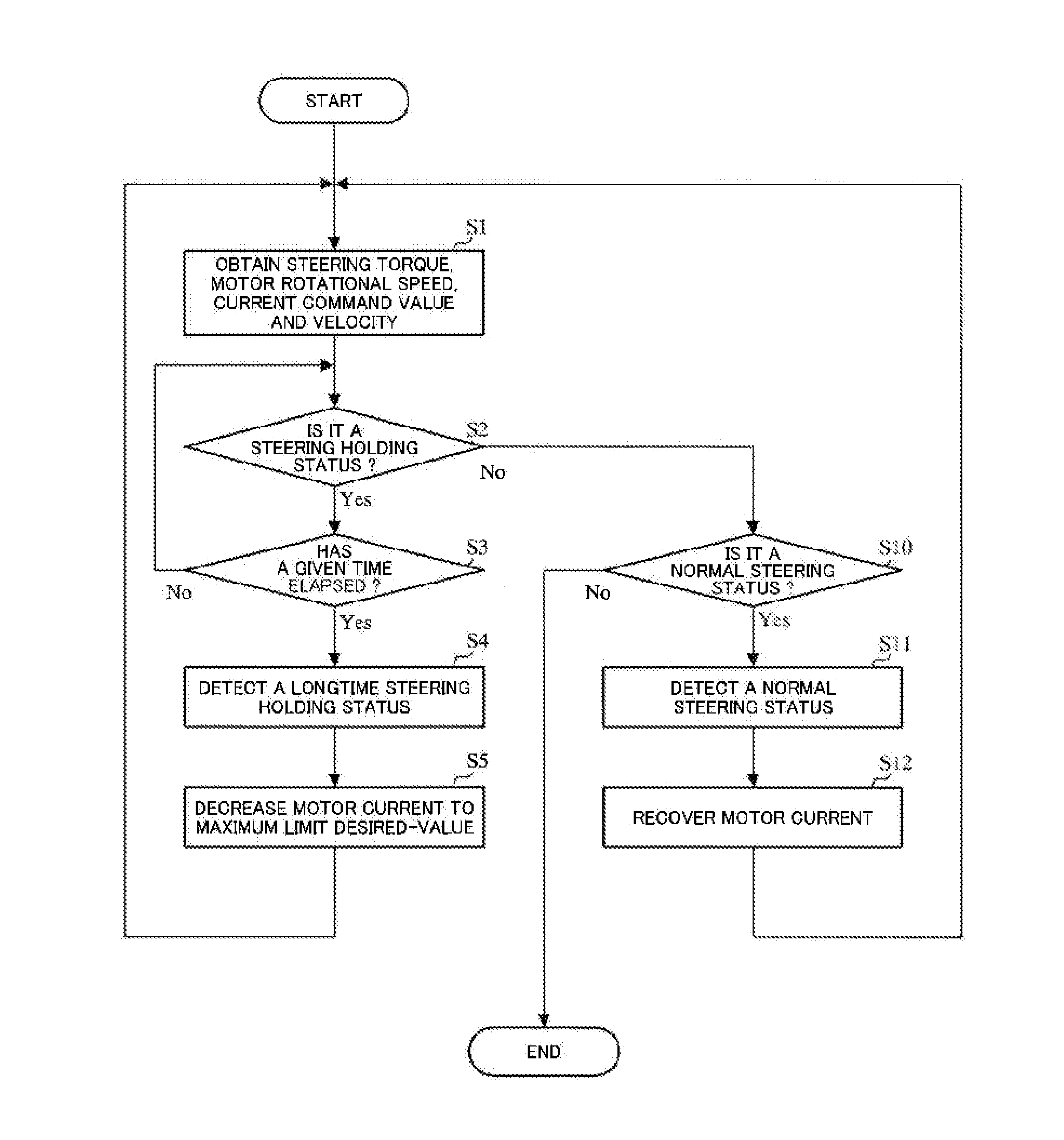
Figure 1 
Figure 2 
Figure 3
Abstract
Description
CROSS-REFERENCE TO RELATED APPLICATIONS
[0001] This is a divisional of U.S. patent application Ser. No. 14 / 131,809, filed Mar. 11, 2014, which is a National Stage of International Application No. PCT / JP2012 / 072356 filed Sep. 3, 2012, claiming priority based on Japanese Patent Application Nos. 2012-022811 and 2012-022814 filed Feb. 6, 2012 and 2012-024209 filed Feb. 7, 2012, the contents of all of which are incorporated herein by reference in their entirety.TECHNICAL FIELD
[0002] The present invention relates to an electric power steering apparatus that provides a steering system of a vehicle with an assist force generated by a brushless DC motor, and in particular to an electric power steering apparatus capable of keeping torque variations at a low level by limiting a continuous energization time of a high current flowing in an electromagnetic type motor relay that supplies a current to the brushless DC motor and controlling so as to gradually decrease the high current flowing in the mo...
Examples
first embodiment
[0063]An electric power steering apparatus according to the present invention (the first embodiment) has been developed to deal with such the situation that a high current flows in the motor relay for a long time in the case that the handle is held for a long time in a status that the motor does not rotate (i.e. in a case that a steering holding status continues a certain time or more). The case that the high current flows in the motor relay for a long time, for example, means the following cases (1)-(4).
[0064](1) a case that the driver holds the steering wheel while a finishing turning of the steering and putting his hands on the steering wheel (that is, applying the torque) in the close vicinity of a rack end, in turning around while waiting for a thing that vehicles going straight ahead for a long time come to an end.
[0065](2) a case that in order to cross railway crossings such as a railway crossing that does not open, a railway crossing with many freight vehicles and so on from...
second embodiment
[0087]FIG. 13 shows a configuration example of the relay-spring-portion-temperature estimating section according to the As shown in FIG. 13, the detected A-phase current value IA, the detected B-phase current value IB and the detected C-phase current IC are inputted into an each-phase current accumulating section 120, an accumulated A-phase current value IAS, an accumulated B-phase current value IBS and an accumulated C-phase current ICS that are accumulated for every phase, are inputted into a maximum value selecting section 121. A maximum value IMS of the accumulated value selected by the maximum value selecting section 121 is inputted into an addition section 122, and a reference temperature RT obtained by an addition performed in the addition section 122 is inputted into a relay-spring-portion-temperature calculating section 123.
[0088]Further, a substrate temperature sensor 140 such as a thermistor sensor or the like is equipped with the substrate, a substrate temperature PT de...
third embodiment
[0101]FIG. 18 shows a configuration example of the relay-coil-portion-temperature estimating section according to the As shown in FIG. 18, the detected A-phase current value IA, the detected B-phase current value IB and the detected C-phase current IC are inputted into an each-phase current accumulating section 120, an accumulated A-phase current value IAS, an accumulated B-phase current value IBS and an accumulated C-phase current ICS that are accumulated for every phase, are inputted into a maximum value selecting section 121. A maximum value IMS of the accumulated value selected by the maximum value selecting section 121 is inputted into an addition section 122, and a reference temperature RT obtained by an addition performed in the addition section 122 is inputted into a relay-coil-portion-temperature calculating section 130.
[0102]Further, a substrate temperature sensor 140 such as a thermistor sensor or the like is equipped with the substrate, a substrate temperature PT detect...