
Power supply system
a power supply system and power supply technology, applied in the direction of parallel/serial switching, battery/fuel cell control arrangement, transportation and packaging, etc., can solve the problems of enlargement degradation of battery components, and achieve the effect of high charge, positive impact on the environment, and high level of charg
Patent Information
- Authority / Receiving Office
- US · United States
- Patent Type
- Applications(United States)
- Current Assignee / Owner
- Publication Date
- 2016-10-27
Smart Images
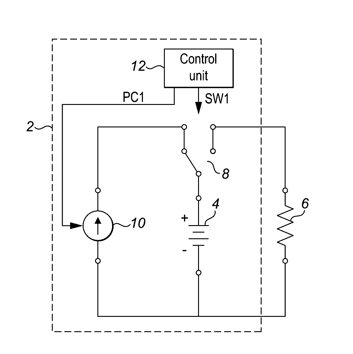
Figure 1 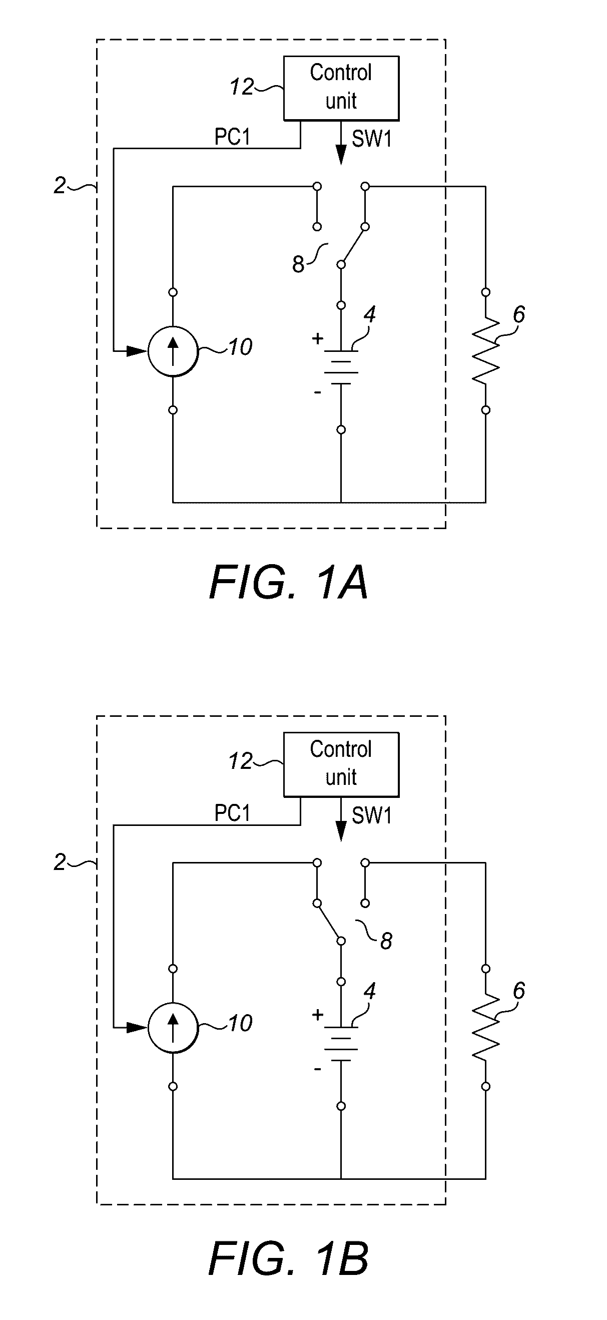
Figure 2 
Figure 3
Abstract
Description
[0001] The invention relates to a power supply system comprising an electrical battery for supplying an electrical load. In particular, the invention relates to a power supply system and / or control system that can enhance the efficiency of operation of a battery.BACKGROUND
[0002] Batteries are ubiquitous in modern day technology. Batteries are available in a wide range of types, each specialised for particular applications, from small button cell batteries used in watches, larger Li-ion batteries used in mobile devices, to large industrial scale batteries. There is often a trade-off between the physical size of the battery versus the capacity required for the battery's application, the two of which are directly related.
[0003] An important subclass of batteries is rechargeable batteries, which provide the functionality of being able to be used repeatedly. Rechargeable batteries are the power source of choice for most portable applications, from cellphones and tablets, to electric motors ...
Examples
Embodiment Construction
[0053]FIGS. 1A and 1B are simplified circuit diagrams of an example power supply system 2. The power supply system 2 includes a battery 4 which is connected in series to a load 6 by a two way switch 8. The power supply 2 system drives the load by supplying an electrical current. A power source 10 is connected to the other terminal of the two way switch 8. FIG. 1A shows the circuit in the configuration where the two-way switch 8 is connected to the load 6 so that the battery 4 supplies power to the load 6. FIG. 1B shows the alternative arrangement where the two way switch 8 is connected to the power source 10 so that the battery 4 can be recharged. The control unit 12 is configured to generate a switching signal SW1. The switching signal SW1 activates the switch 8 causing it to switch periodically between its two positions.
[0054]In FIG. 1A when the switch 8 is closed between the battery 4 and the load 6, current flows from the battery 4 to the load 6. This results in a discharge of t...