
Error identification method of machine tool and error identification system of the same
a technology of error identification and machine tools, which is applied in the direction of mechanical measuring arrangements, manufacturing tools, instruments, etc., can solve the problems of deteriorating process accuracy of workpieces, difficult to zero geometric errors, and deteriorating motion accuracy of machines, so as to reduce the load of operators of machines, not deteriorating the measurement accuracy of position measurement sensors, and reliably performing the calibration of position measurement sensors
Patent Information
- Authority / Receiving Office
- US · United States
- Current Assignee / Owner
- Publication Date
- 2017-10-19
Smart Images
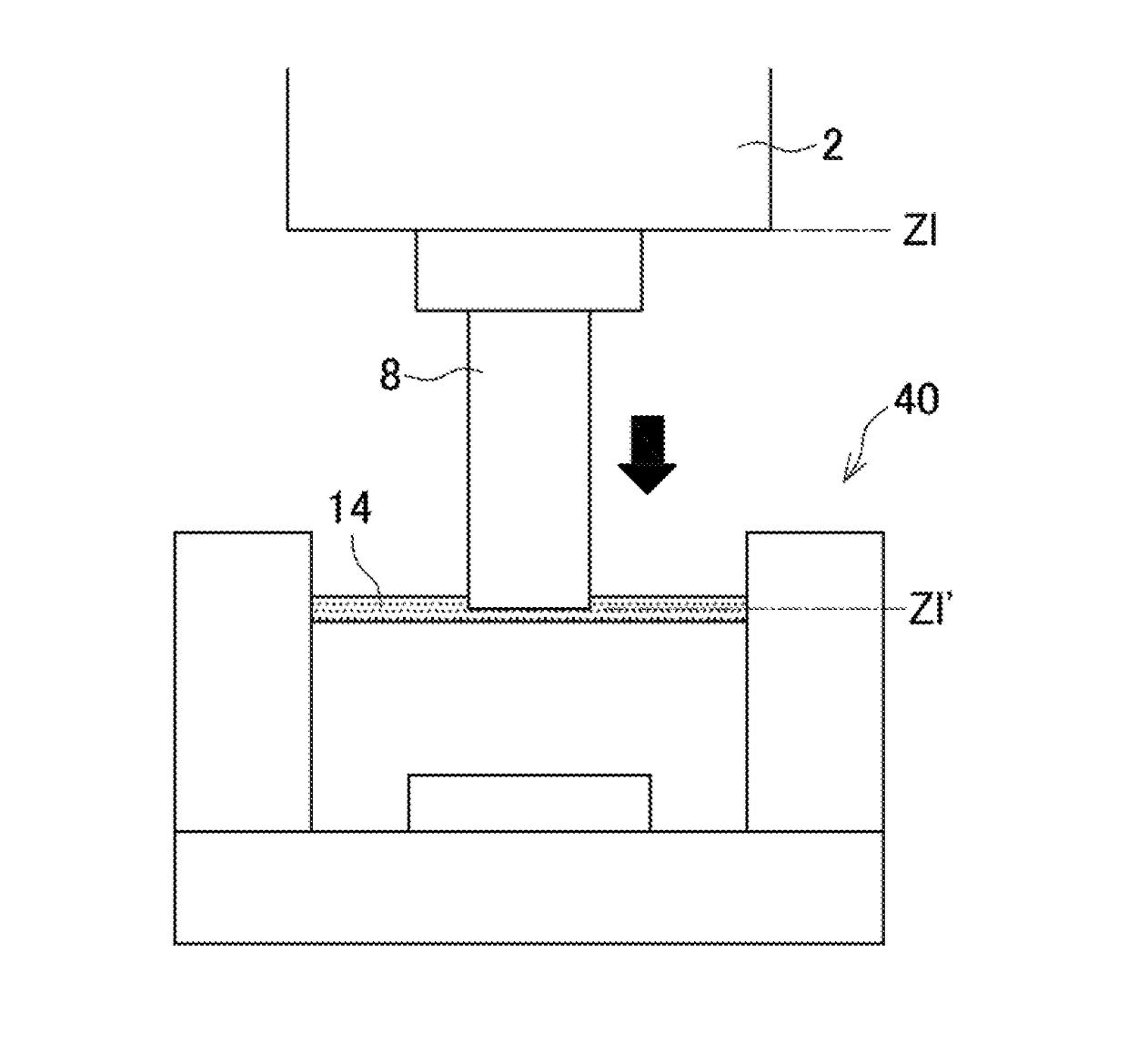
Figure 1 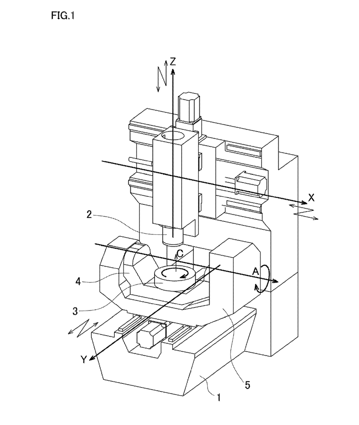
Figure 2 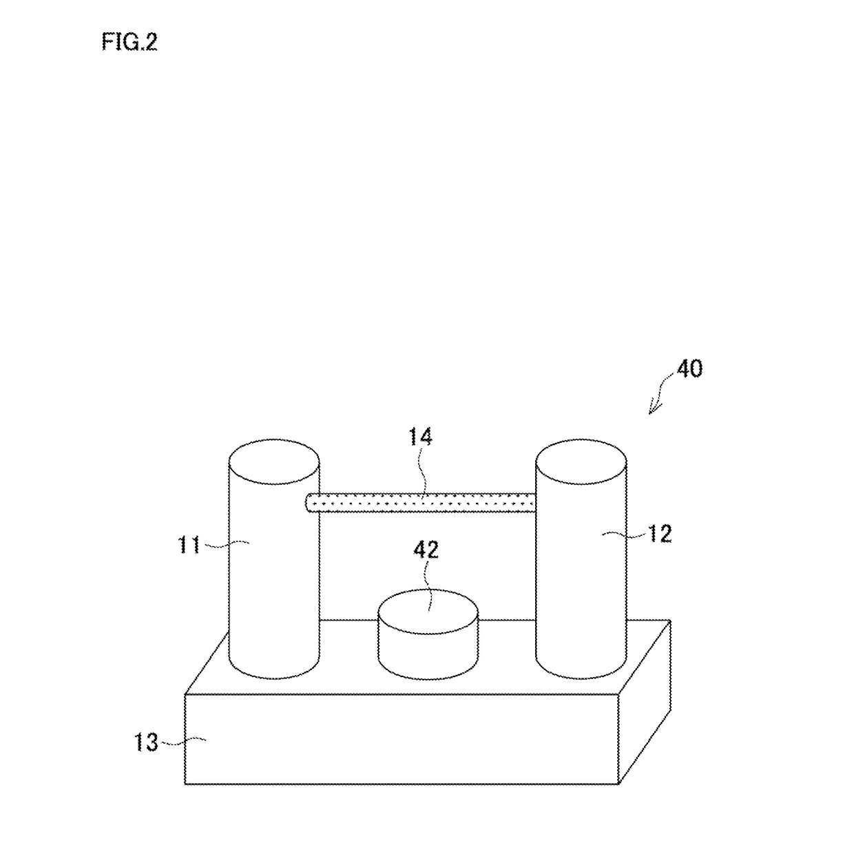
Figure 3
Abstract
Description
BACKGROUND
[0001] This application claims the benefit of Japanese Patent Application Numbers 2016-083860 filed on Apr. 19, 2016 and 2017-019723 filed on Feb. 6, 2017, the entirety of which is incorporated by reference.TECHNICAL FIELD
[0002] The disclosure relates to a method that identifies a geometric error in a machine tool from a measurement result of a position of an object in the machine and a system that identifies the geometric error.RELATED ART
[0003] FIG. 1 is a schematic diagram of a five-axis-control machining center that includes three translational axes and two rotation axes. A motion of two degrees of freedom for translation of a main spindle 2 in an X-axis and a Z-axis, which are the translational axes and are orthogonal to one another, is possible with respect to a bed 1. A motion of one degree of freedom for rotation of a table 3 in a C-axis, which is the rotation axis, is possible with respect to a cradle 4. A motion of one degree of freedom for rotation of the cradle 4 ...
Examples
Embodiment Construction
[0057]The following describes embodiments of the disclosure based on the drawings.
[0058]FIG. 1 is a schematic diagram of a machining center, which is one configuration of a machine tool, that includes three translational axes orthogonal to one another and two rotation axes orthogonal to one another. A motion of two degrees of freedom for translation of a main spindle 2 in an X-axis and a Z-axis, which are the translational axes and are orthogonal to one another, is possible with respect to a bed 1. A motion of one degree of freedom for rotation of a table 3 in a C-axis, which is the rotation axis, is possible with respect to a cradle 4. A motion of one degree of freedom for rotation of the cradle 4 in an A-axis, which is the rotation axis orthogonal to the C-axis, is possible with respect to a trunnion 5. A motion of one degree of freedom for translation of the trunnion 5 in a Y-axis, which is the translational axis and orthogonal to the X-axis and the Z-axis, is possible with respe...