
Method and a system for radio transmission
a radio transmission and radio technology, applied in the field of radio transmission methods and systems, can solve the problems of inability to use frequency diversity systems and other types of diversity systems to increase the required frequency range, and may not be feasible for long distances
Patent Information
- Authority / Receiving Office
- US · United States
- Patent Type
- Patents(United States)
- Current Assignee / Owner
- Publication Date
- 2003-02-25
- Estimated Expiration
- Not applicable · inactive patent
Smart Images
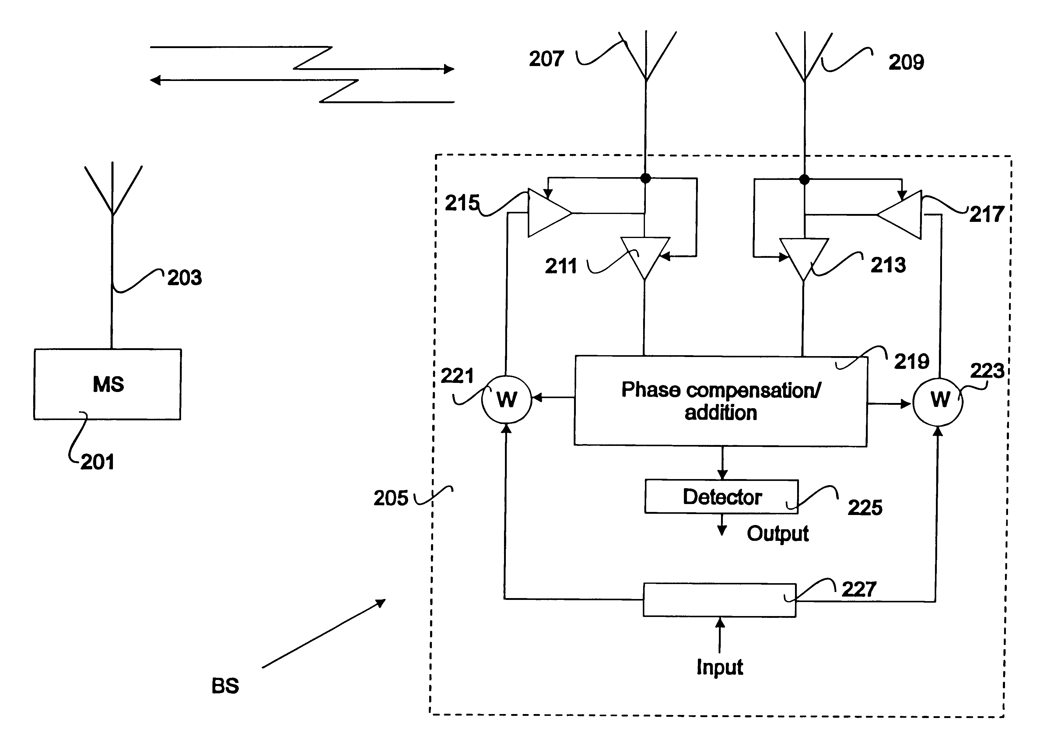
Figure 1 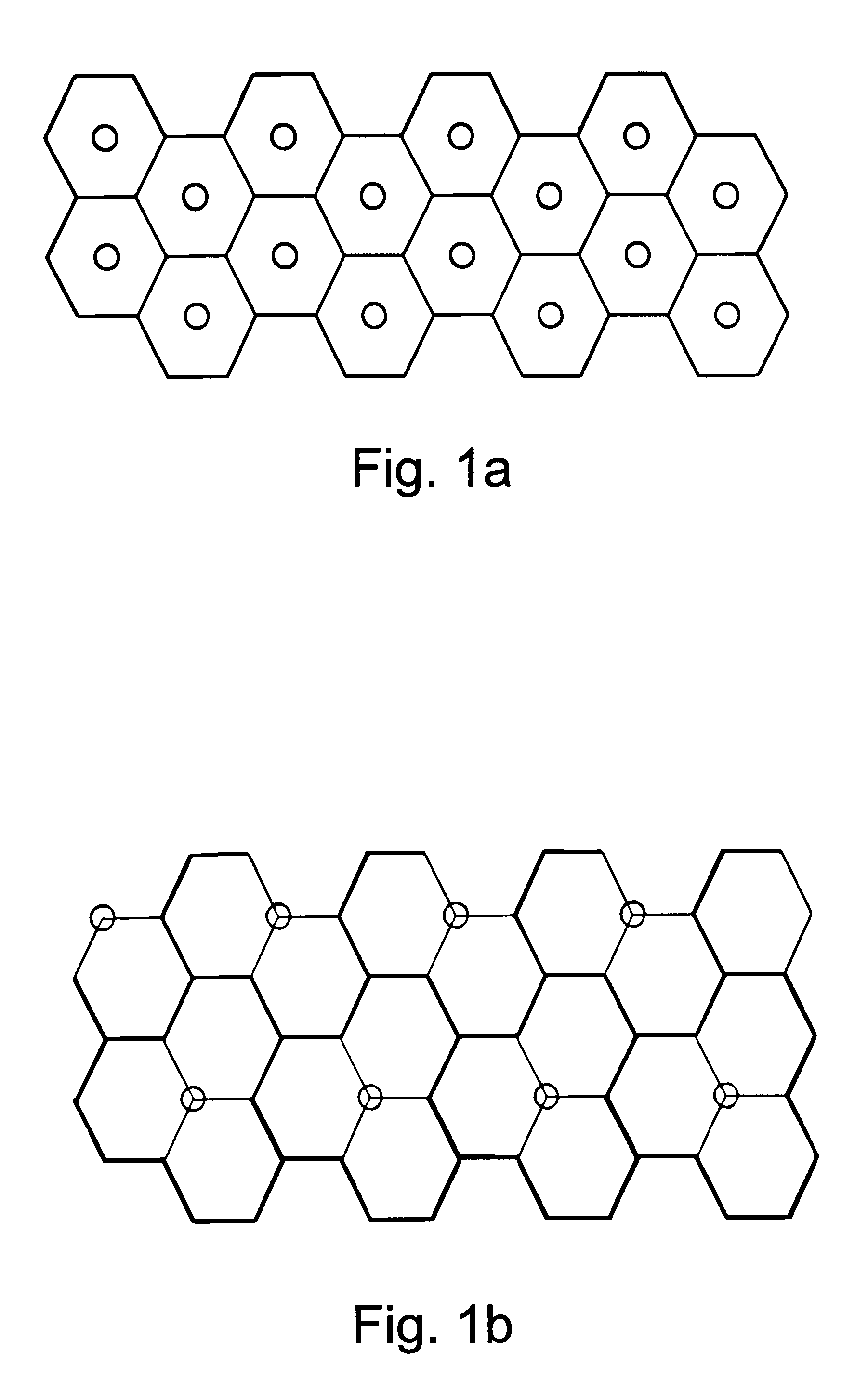
Figure 2 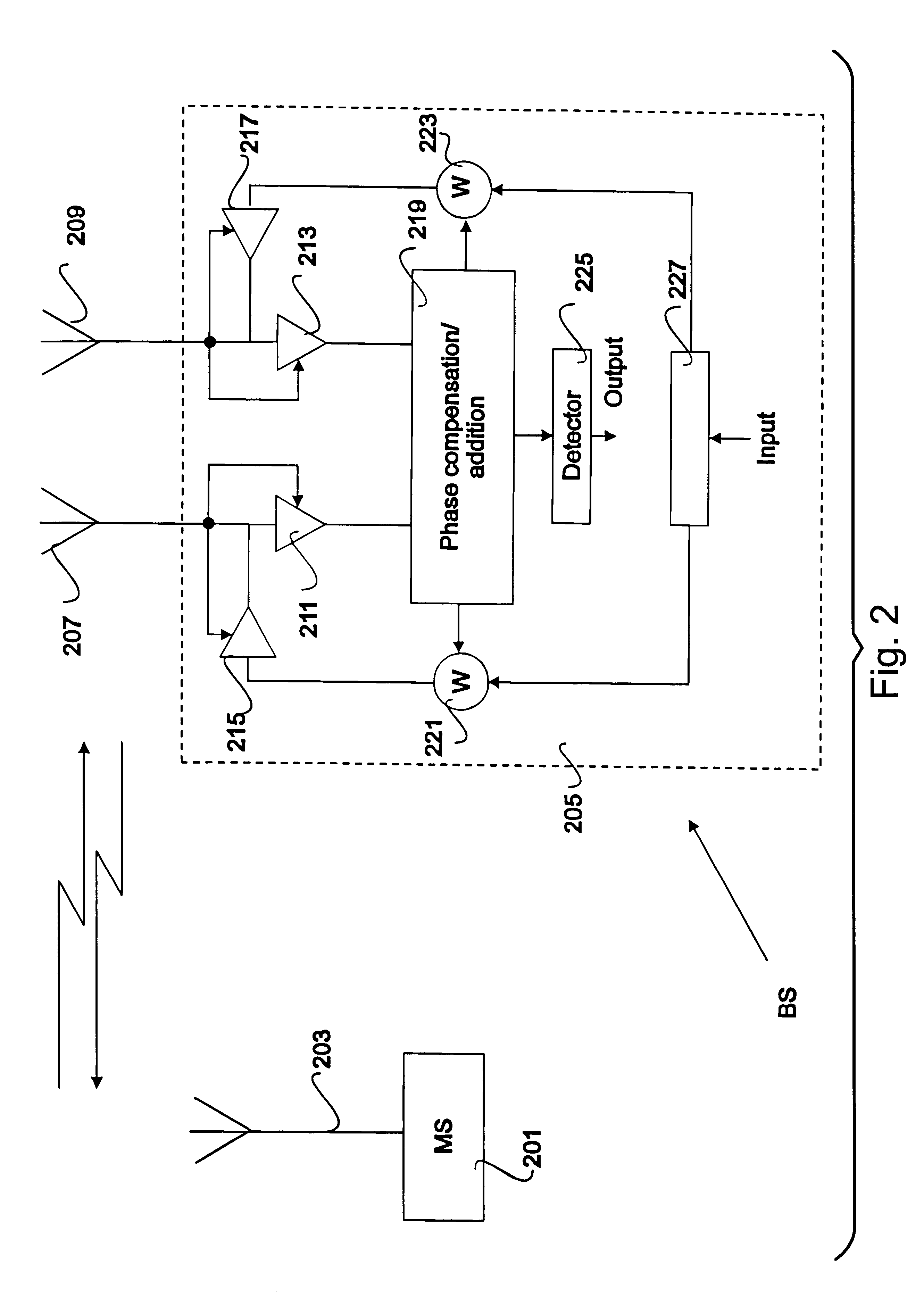
Figure 3
Abstract
Description
The present invention relates to a method and a system for radio communication.DESCRIPTION OF RELATED ARTIn cellular radio systems the number of cells used for covering a particular area should be as small as possible in order to minimize the costs. However, in order to maintain a sufficiently good signal to noise ratio (SNR) for a system having many mobile stations, the cell size should be as small as possible.Thus, using a small cell size the same signals can be reused at other locations in the cellular radio system. In a system having M orthogonal signals or channels these are usually divided into K groups having the same or close to the same number of channels. In a hexagonal cell pattern with the base station located in the middle of the cell, see FIG. 1a, K can be any integer written asK=(i+j).sup.2 -ij,where i,j=0,1,2,3, . . .Thus K can be K=3,4,7,9,12,13, . . .A group of cells where each channel group is used once is usually termed cluster. K is therefore usually termed clus...
Examples
Embodiment Construction
In FIG. 2 a principal view of a cellular radio transmission system is shown. Thus, a mobile station is shown at 201. The mobile station 201 has an antenna 203 by means of which it can communicate with a base station shown at 205. The base station 205 has two antennas 207 and 209.
The base station 205 shown in FIG. 2 is designed for maximum ratio combining diversity. Thus, the SNR is derived from the signals received by the antennas 207 and 209. The SNRs are used for setting amplifiers 211 and 213 to values corresponding to the measured SNRs. In other words, the receiving branch having a better SNR will be more amplified than the receiving branch having a small SNR.
The same value as is set for the amplifier 211 is at the same time set for an amplifier 215 and the same value set for the amplifier 213 is set for an amplifier 217. The amplifiers 215 and 217 form a part of the transmission circuit of the base station 205 and are also connected to the antennas 207 and 209, which thus are u...