
Electronically agile multi-beam antenna
a multi-beam antenna, electromagnetic technology, applied in the direction of antennas, antenna adaptation in movable bodies, instruments, etc., can solve the problems of increasing the difficulty of radar antenna system technology to provide sufficient information, the current radar antenna system is generally proving inadequate in terms of detection range, field of view, resolution, or combinations, and the radar antenna system may not be able to provide information on the other aircraft in time to avoid a collision
Patent Information
- Authority / Receiving Office
- US · United States
- Patent Type
- Patents(United States)
- Current Assignee / Owner
- Publication Date
- 2004-08-03
- Estimated Expiration
- Not applicable · inactive patent
Smart Images
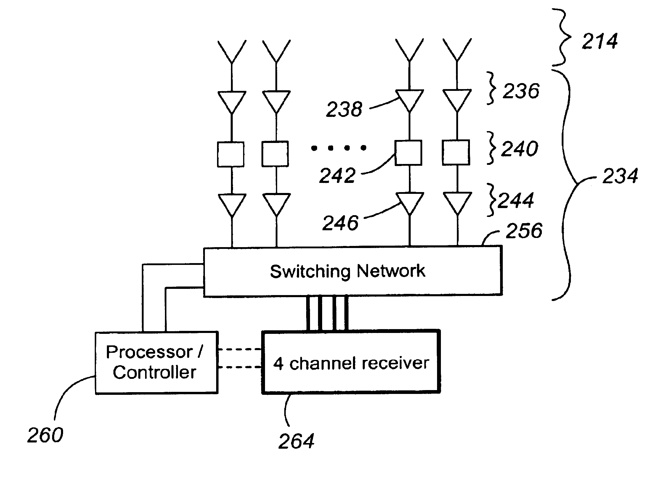
Figure 1 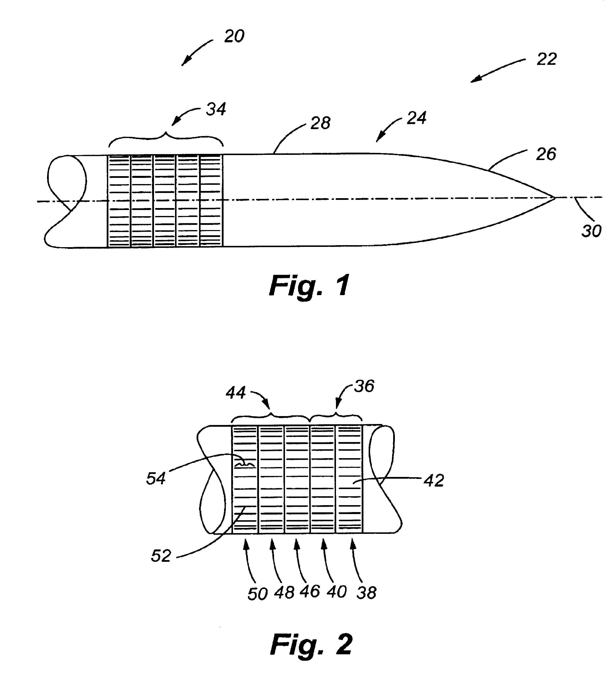
Figure 2 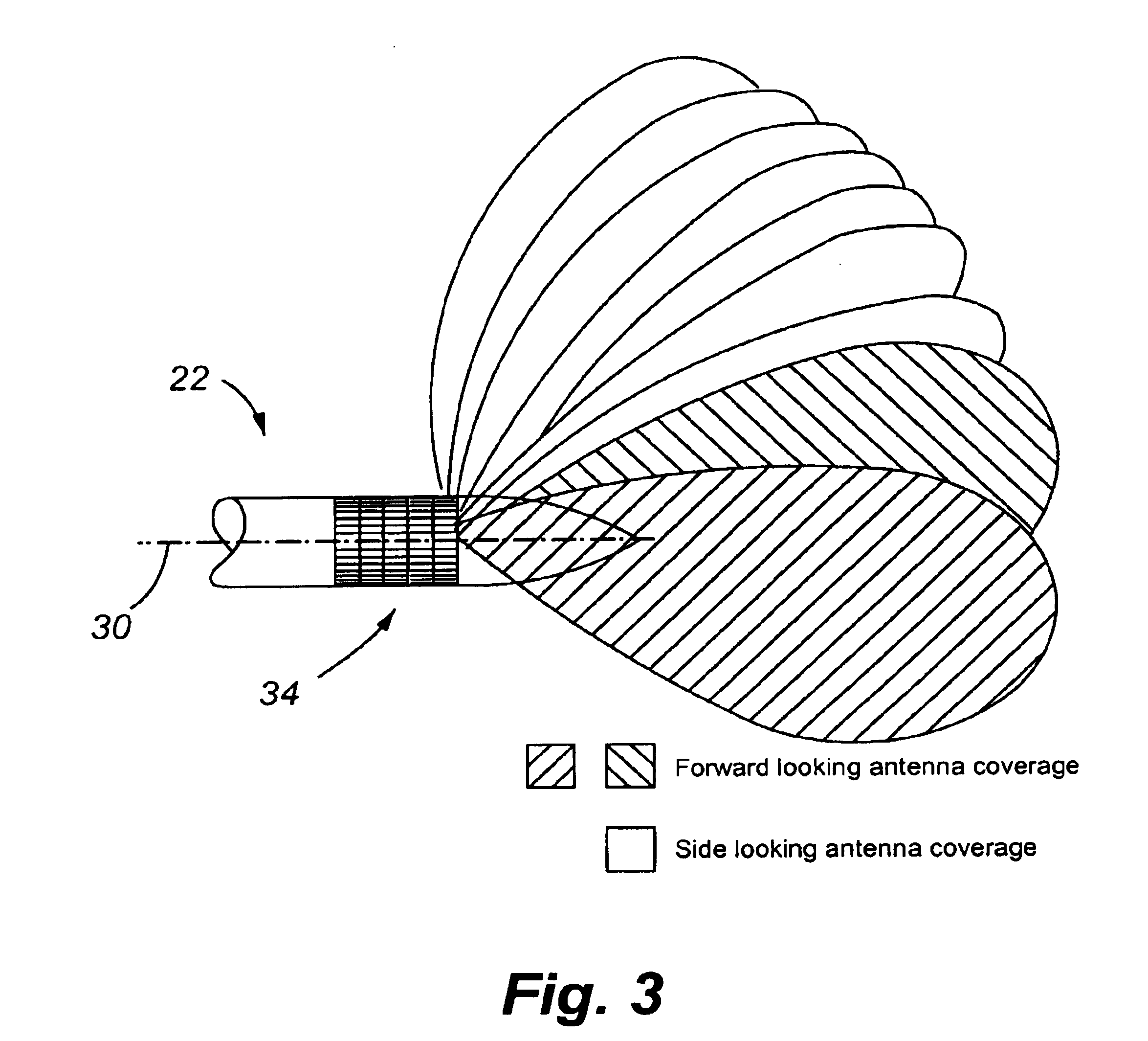
Figure 3
Abstract
Description
1. Field of the InventionThe present invention relates to antenna systems and, in particular, to an antenna system that uses a multi-element antenna array to receive an electromagnetic signal and generate a plurality of electrical signals that are representative of the received electromagnetic signal and a multi-beam beamformer to produce at least two spatially independent, overlapping beams from the electrical signals provided by the array.2. Description of the Related ArtPresently, antenna systems are used in many aeronautical applications. One application for an antenna system is as part of a radar on an aircraft where the antenna system is used to obtain positional information on the objects in the space surrounding the aircraft. This positional information is then typically used to either avoid an object, such as another aircraft, or to home in on an object, such as a navigational beacon.Present radar antenna system technology is becoming increasingly hard-pressed to provide su...
Examples
first embodiment
FIG. 1 illustrates the antenna system of the present invention 20, hereinafter referred to as antenna system 20. The antenna system 20 is part of a radar that is located on an aircraft 22 which has an exterior surface 24 comprised of a front or nose surface 26, a cylindrical side surface 28, and a longitudinal axis 30 that also defines the direction of movement of the aircraft 22. To distinguish the nose surface 26 from the side surface 28, any point on the nose surface 26 has a surface area vector that is other than perpendicular to the longitudinal axis 30 and any point on the side surface has an area vector that is substantially perpendicular to the longitudinal axis 30.
The antenna system 20 includes an antenna array 34 that is mounted on the side surface 28 of the aircraft 22 such that it has a low profile with respect to the side surface 28. In this case, the antenna array is substantially conformal with the side surface 28. The low-profile or conformal mounting of the antenna ...
second embodiment
With reference to FIG. 11, the antenna system 20 is illustrated. This embodiment of the antenna system 20 is useful in reducing the possibility of the signals that are being transmitted or received by the antenna system being intercepted and is also capable of being used in low SNR environments. The antenna system 20 includes a surface 150 that is comprised of eight facets 152 that each support a portion of the antenna array. More specifically, each facet 152 supports two column arrays 154 that are separated from one another. Each of the column arrays 154 is comprised of a plurality of vertically juxtaposed subarrays 156. Each subarray 156 is, in turn, comprised of four horizontally juxtaposed antenna elements 158. The antenna element 158 is a nine dipole asymmetric log periodic antenna element. The spacing between the antenna elements 158 comprising the subarray 156 is tapered in depth so that a frequency-independent azimuth beamwidth is realized across the frequency bandwidth of t...
third embodiment
FIG. 16 illustrates the antenna system 20. The antenna system 20 is part of a radar that is located on an aircraft 202 which has an exterior surface 204 comprised of a front or nose surface 206, a cylindrical side surface 208, and a longitudinal axis 210 that also defines the direction of movement of the aircraft 202. To distinguish the nose surface 206 from the cylindrical side surface 208, any point on the nose surface 206 has a surface area vector that is other than perpendicular to the longitudinal axis 210 and any point on the side surface has a surface area vector that is substantially perpendicular to the longitudinal axis 210.
The antenna system 20 includes a forward-looking receive array 214 for receiving electromagnetic signals from a source in a defined field of view (FOV) and converting these electromagnetic signals into electrical signals from which beams can be formed that can be used to determine information on the source of the electromagnetic radiation, which is here...