

Ultra-broadband differential voltage probes
a differential voltage and probe technology, applied in the field of wideband differential voltage probes, can solve the problems of affecting the accuracy of measurement results, so as to minimize parasitic inductance and capacitance, and maximize the amount of power carried
Patent Information
- Authority / Receiving Office
- US · United States
- Patent Type
- Patents(United States)
- Current Assignee / Owner
- Publication Date
- 2006-03-21
Smart Images
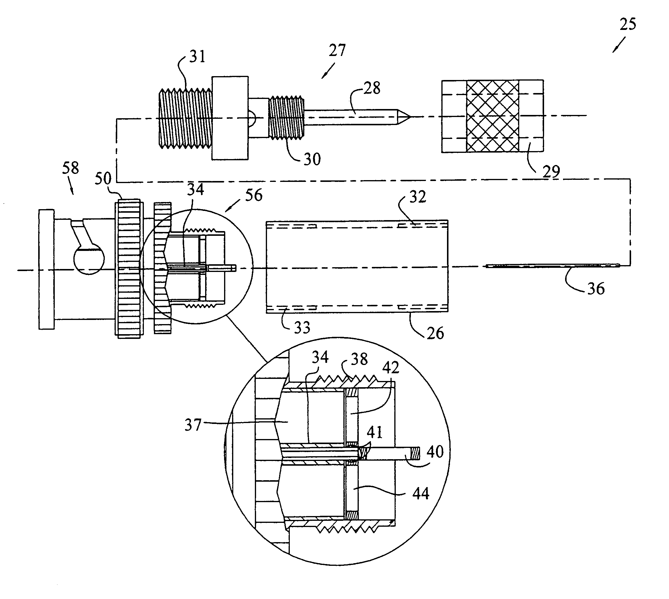
Figure 1 
Figure 2 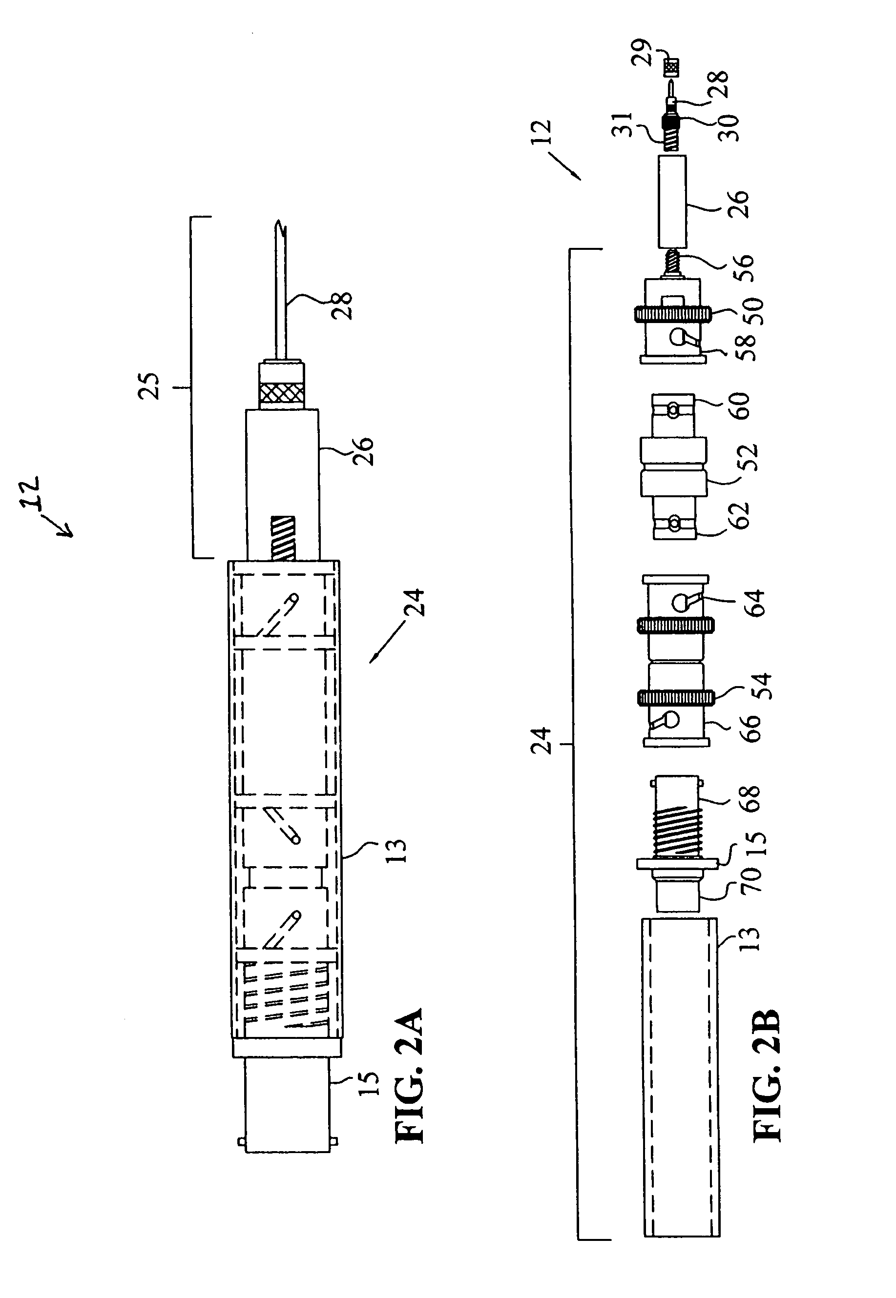
Figure 3
Abstract
Description
TECHNICAL BACKGROUND
[0001] The present invention generally relates to high frequency measurement equipment, and, more particularly, the invention relates to wideband differential voltage probes.BACKGROUND OF THE INVENTION
[0002] Oscilloscopes, spectrum analyzers, and other signal analysis devices are generally used to measure a voltage signal between two points with one of the points often being referenced to earth ground. However, in many cases it is advantageous to measure the voltage between two points in a circuit with neither of the points being the ground to which the signal analysis device is referenced.
[0003] If the ground of the signal analysis device is connected to the ground of the circuit under test, a ground loop may result. The ground loop may act as a secondary transformer winding, thus producing a magnetic field and creating a signal in nearby conductors, such as the probe used to connect the signal analysis device with the circuit under test. Additionally, current and ...
Examples
Embodiment Construction
[0027]The embodiment disclosed below is not intended to be exhaustive or limit the invention to the precise forms disclosed in the following detailed description. Rather, the embodiment is chosen and described so that others skilled in the art may utilize its teachings.
[0028]Referring to FIG. 3, balanced probe pair assembly 10 includes probes 12, coaxial cables 14, and may include ground lead 16. Assembly 10 may be coupled to input channel connector 22 of signal analysis device 18 using, for example, combiner 20. Referring to FIG. 2A, each probe 12 includes probe body 24, probe end 25, body sleeve 13, and base connector 15.
[0029]Referring to FIG. 1, each probe end 25 includes a probe tip sleeve 26, a coupling probe end connector 50 and a probe tip 27. Probe tip 27 includes an elongate tip 28, a threaded sleeve 29, a distal tip thread 30, and a proximate tip thread 31. Threaded sleeve 29 engages a distal tip thread 30 and proximate tip thread 31 engages a distal sleeve thread 32 of p...