
Energy efficient fluid pump
a fluid pump and energy-saving technology, applied in the direction of machines/engines, mechanical equipment, pressure lubrication, etc., can solve the problems of significant energy loss, alternation acceleration and deceleration of crankshaft rotation, firing and compression strokes, and the rotation of the crankshaft is accelerated and decelerated. , to achieve the effect of increasing the efficiency of the pump system and reducing nois
Patent Information
- Authority / Receiving Office
- US · United States
- Current Assignee / Owner
- Publication Date
- 2006-08-08
- Estimated Expiration
- Not applicable · inactive patent
Smart Images
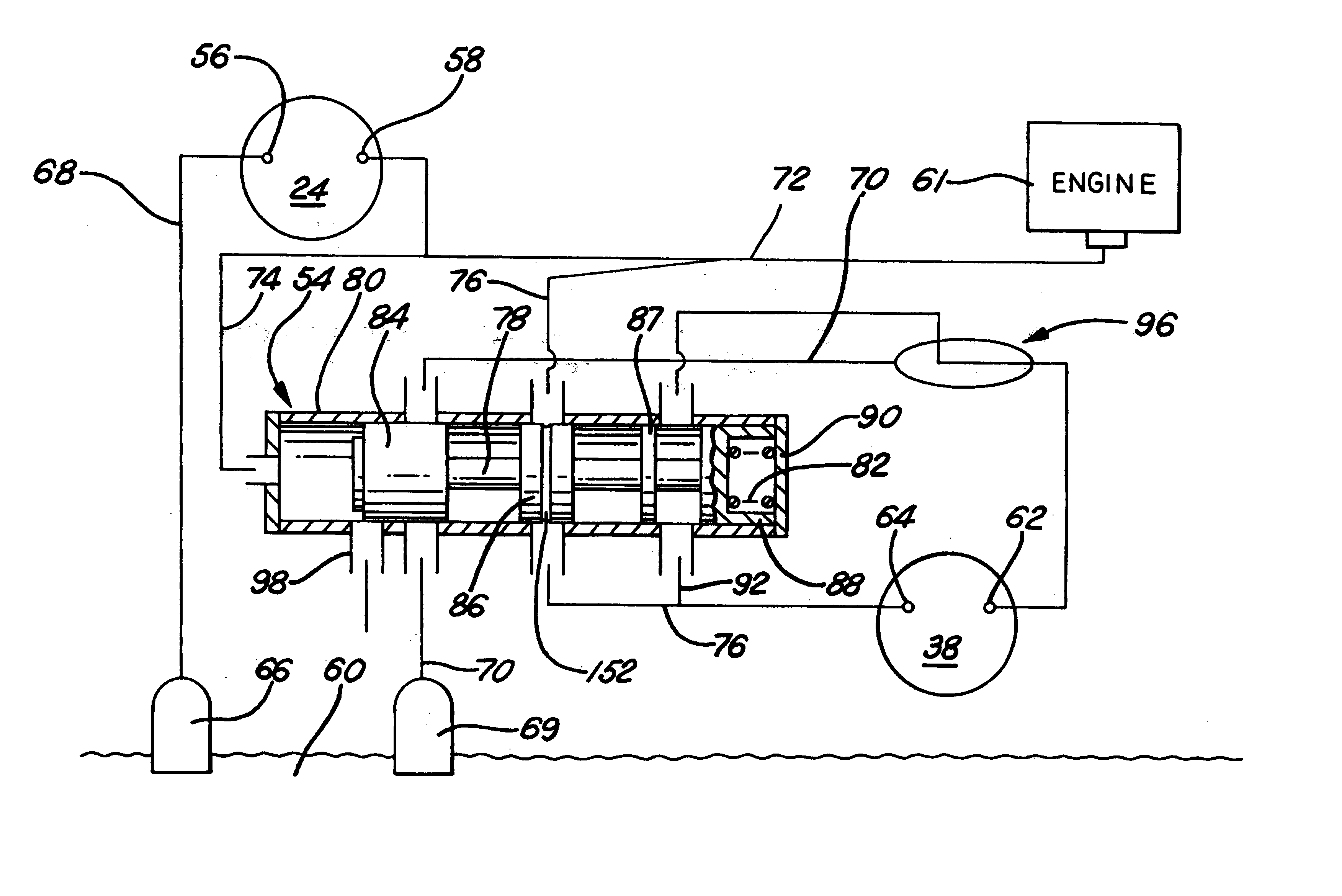
Figure 1 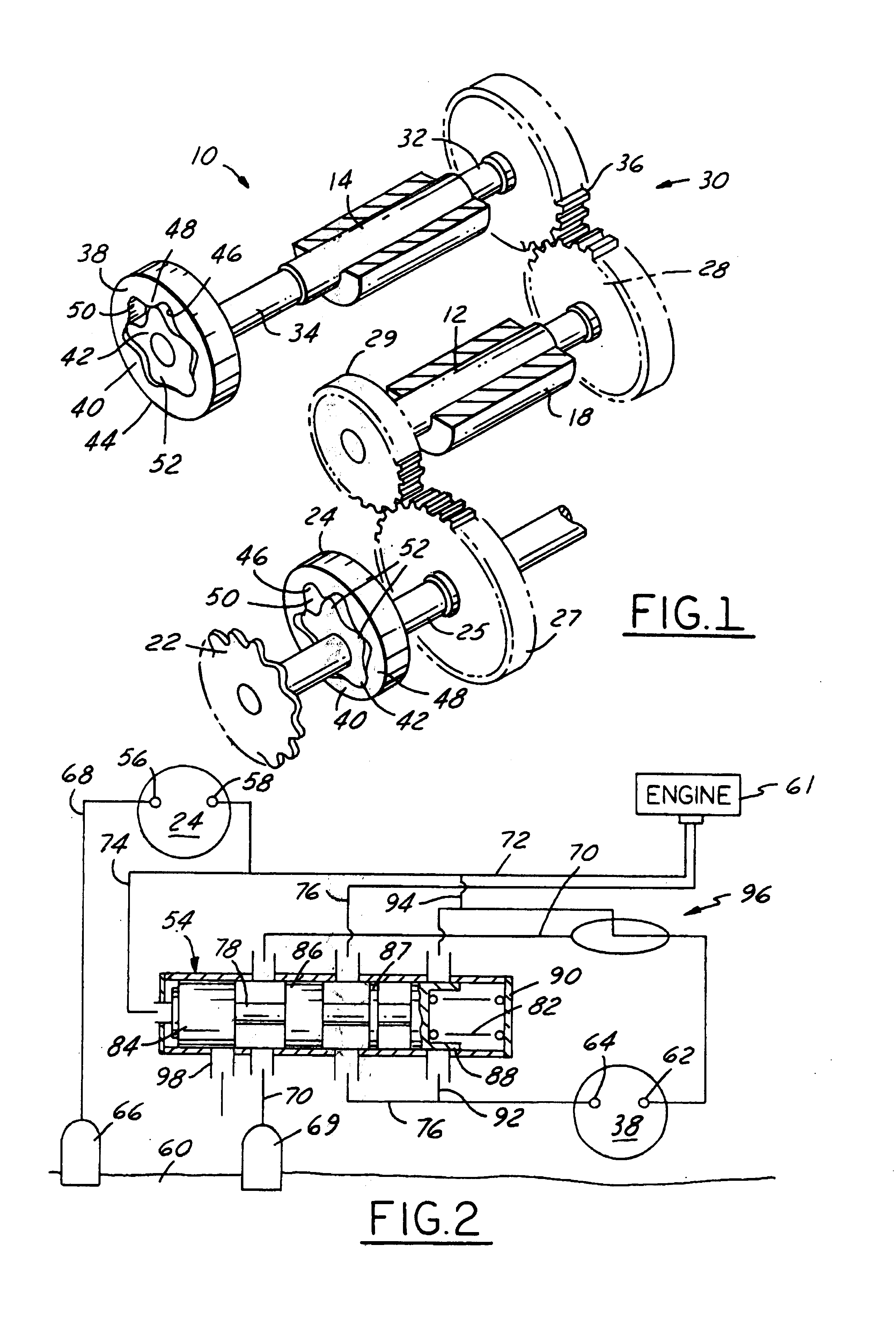
Figure 2 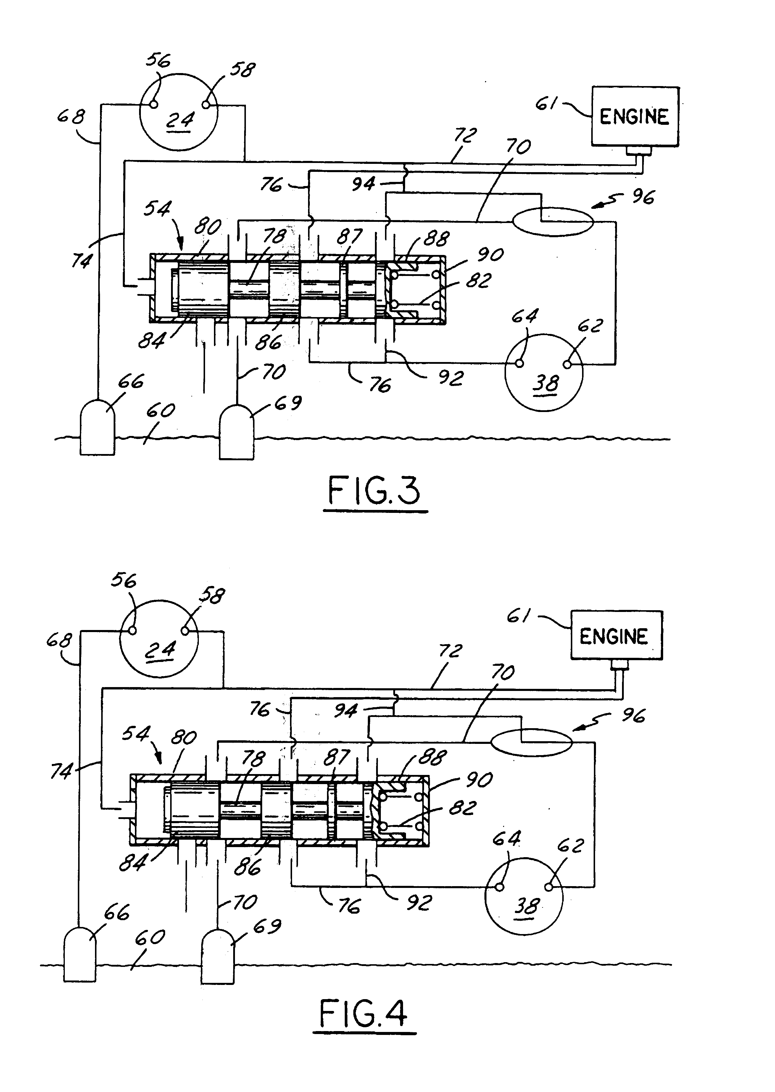
Figure 3
Abstract
Description
CROSS-REFERENCE TO RELATED APPLICATIONS
[0001] The present application claims the benefit of Provisional Application Ser. No 60 / 130,103, filed Apr. 20, 1999.TECHNICAL FIELD
[0002] The present invention relates to a fluid pump system for an engine or other system. More specifically, the present invention relates to a dual pumping element system which allows for the reduction of driving power consumption by effectively switching one pump element out of the system when the engine is operating above a pre-determined fluid pressure.BACKGROUND OF THE INVENTION
[0003] Fluid pump systems, and specifically oil pump systems, are well known in the art. In a typical oil pump system, the oil pump is driven by an engine s crankshaft and is either located on the front of the engine or in the oil pan. Because the oil pump is driven by the crankshaft, it runs at a fixed speed ratio to the engine crankshaft, which ratio is determined by the flow volume required to maintain oil pressure at low speeds. This ...
Examples
Embodiment Construction
[0031]Preferred embodiments of the present invention are shown in the drawings. Referring now to FIGS. 1 through 6, a preferred embodiment of an oil pump system 10, in accordance with the present invention, is disclosed. The present invention is not limited to an oil pump system and may be utilized in any fluid pumping system with a variety of other fluids. The following description of an oil pump system is merely illustrative will be understood as such by one of skill in the art.
[0032]The type of oil pump used with the present invention is preferably a positive displacement oil pump. Pumps of this type include internal tip-sealing rotors, hereafter referred to as “geroter” pumps, vane pumps, gear pumps, and piston pumps. For purposes of illustrating the present application, a geroter-type pump will be utilized which also constitutes the preferred form of the invention. However, it is to be understood that any pump can be utilized and that the depiction of a geroter pump is simply i...