
Rotary evaporation with variable dosage metering
Patent Information
- Authority / Receiving Office
- US · United States
- Current Assignee / Owner
- Publication Date
- 2006-12-19
- Estimated Expiration
- Not applicable · inactive patent
Smart Images
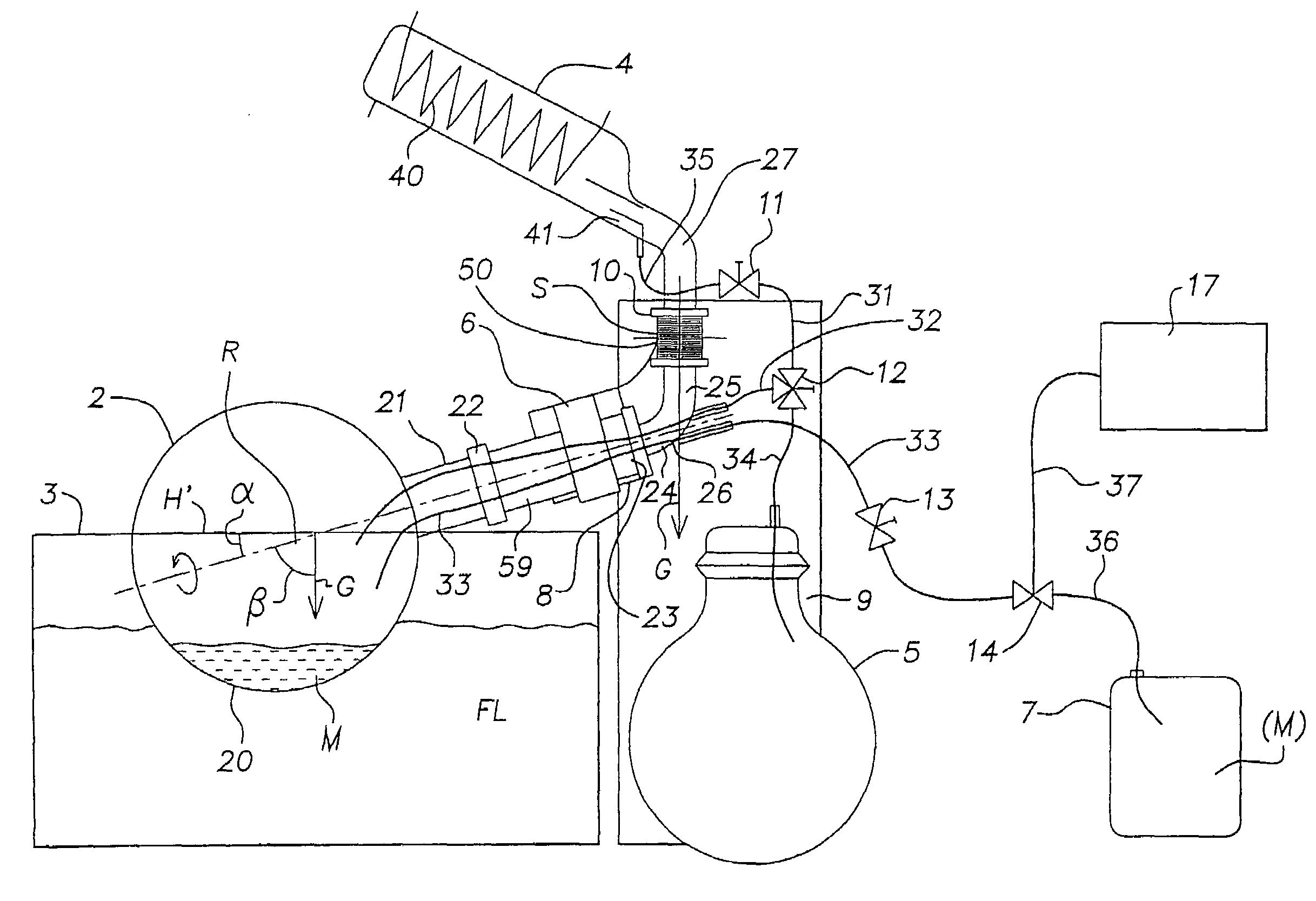
Figure 1 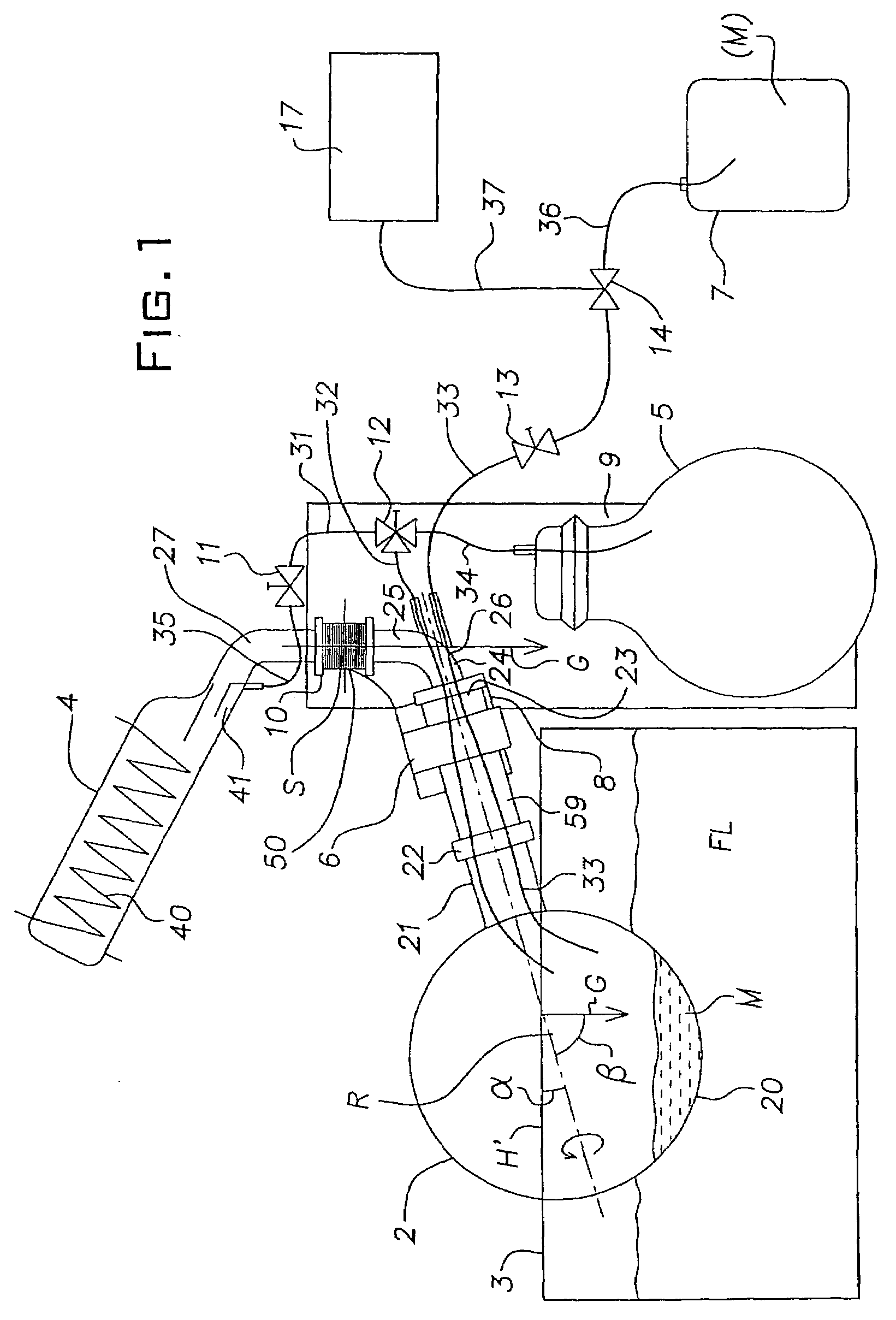
Figure 2 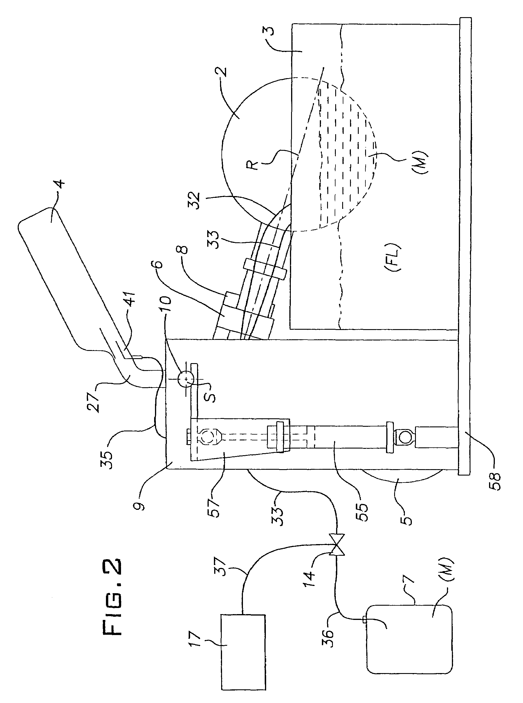
Figure 3
Abstract
Description
BACKGROUND OF THE INVENTION
[0001] This invention relates to a method and a system for evaporating at least one substance.
[0002] There have been prior-art systems, referred to as rotary evaporators, serving for the evaporation of substances and especially of solvents in the process of concentrating or distilling pharmaceutical or chemical products. In these prior-art rotary evaporators the liquid substances to be evaporated are introduced into the interior space of a rotating flask (evaporating vessel) typically designed to rotate within a thermal bath. As the rotating flask revolves, a thin film of liquid forms on the inside of the rotating flask from which film the substances, in particular the solvent, will then evaporate. A certain amount of the substance, i.e. of the solvent, also evaporates directly from the surface level of the liquid in the rotating flask. From the rotating flask the vapor travels through a vapor conduit toward a condenser where it is reprecipitated by condensa...
Examples
Embodiment Construction
[0057]The rotary evaporator per FIG. 1 and FIG. 2 encompasses a revolving vessel (or working vessel or rotating flask) 2 which can be rotated (turned) by means of a drive system 6 around an axis of rotation R (center of rotation) and in which the substance(s) to be evaporated can be introduced. The revolving vessel 2 per FIGS. 1 and 2 is preferably designed to be rotationally symmetrical to the axis of rotation R as the axis of symmetry, making it, when empty, rotatable around its main axis of inertia without any imbalance. The revolving vessel 2 includes an essentially spherical receptacle 20 designed to hold a product M containing liquid or particulate substance(s) to be evaporated, and, extending from an opening in the spherical receptacle 20, a neck 21 which by way of a flange 22 connects to a sleeve-type shaft 59 that is or can be rotated by the drive system 6.
[0058]For rotating the revolving vessel 2, the drive system 6 includes an electric drive unit or motor, not illustrated...