
Cutting apparatus
a cutting machine and cutting blade technology, applied in the field of cutting machines, can solve the problems of increasing the cost of the apparatus, reducing the working efficiency, and deteriorating the dimensional accuracy of cutting, so as to prevent the increase of the apparatus cost, reduce the working efficiency, and improve the cutting accuracy. the effect of cutting accuracy
Patent Information
- Authority / Receiving Office
- US · United States
- Patent Type
- Patents(United States)
- Current Assignee / Owner
- Publication Date
- 2007-04-24
- Estimated Expiration
- Not applicable · inactive patent
Smart Images
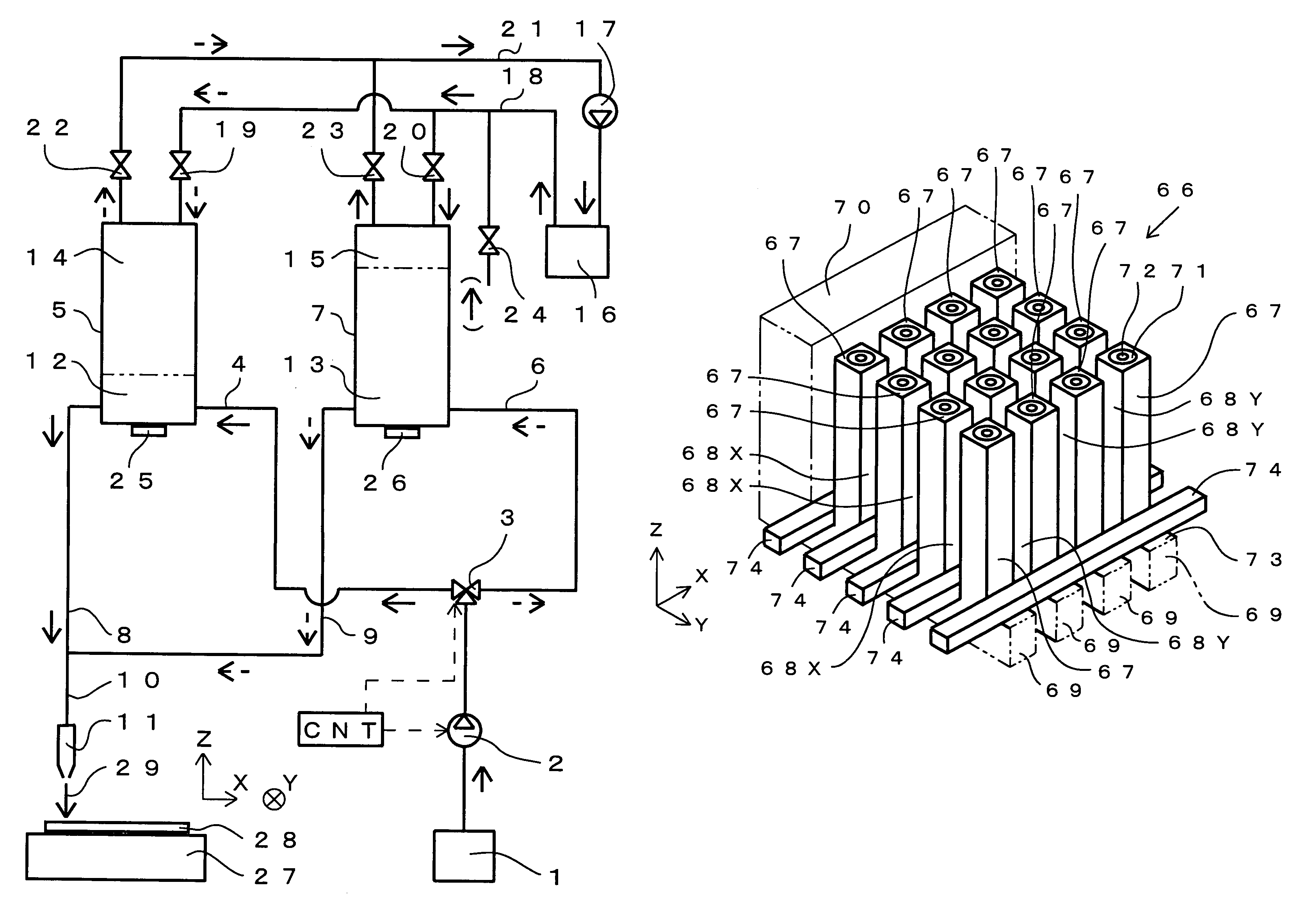
Figure 1 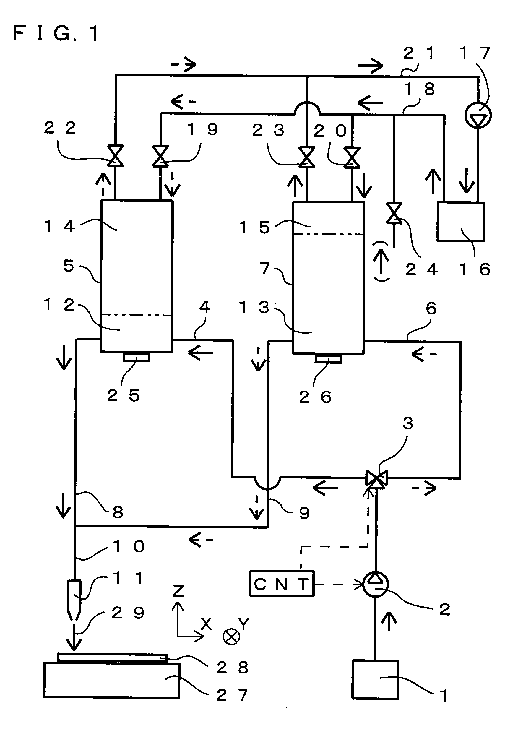
Figure 2 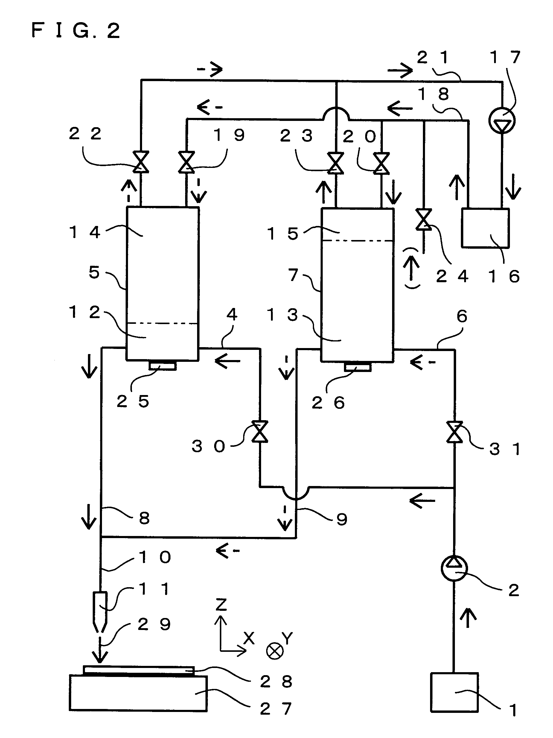
Figure 3
Abstract
Description
[0001] This nonprovisional application is based on Japanese Patent Application No. 2005-276904 filed with the Japan Patent Office on Sep. 22, 2005, the entire contents of which are hereby incorporated by reference.BACKGROUND OF THE INVENTION
[0002] 1. Field of the Invention
[0003] The present invention relates to a cutting apparatus using water containing abrasive grains.
[0004] 2. Description of the Background Art
[0005] A description is given of conventional cutting apparatus and cutting method using water containing abrasive grains. This method was invented for the purpose of improving machining efficiency of a method of cutting a workpiece by jetting high-pressure water to the workpiece (so-called waterjet cutting) (for example, Japanese Patent Laying-Open No. 2000-000767, pages 2–4, FIGS. 1–4). The method uses, as an abrasive (abrasive grains), garnet, silica sand or cast steel grit for example. The abrasive in wet state is supplied from an abrasive tank via an abrasive supply pipe and,...
Examples
first embodiment
[0027]A first embodiment of the cutting apparatus according to the present invention is described with reference to FIG. 1. FIG. 1 is a diagram of a pipe system, schematically showing a structure of the cutting apparatus according to the present embodiment. It is noted that any drawing referred to in the following description is schematically shown in which some parts are not shown or some parts are emphasized where appropriate for the sake of easy understanding. Moreover, in connection with the following embodiments each, a description is given of a case where an encapsulated body in which semiconductor chips or the like mounted on a circuit board are encapsulated all together in resin is cut along grid-pattern cutting lines intersecting at right angles. In this case, a highly accurate cutting position as well as a cutting width of approximately 200 μm are required.
[0028]The cutting apparatus shown in FIG. 1 has a system of jetting water containing abrasive grains at a high pressur...
second embodiment
[0047]With reference to FIG. 2, a second embodiment of the cutting apparatus according to the present invention is described. FIG. 2 is a diagram of a pipe system, schematically showing a structure of the cutting apparatus according to the present embodiment. In any drawing referred to in the following description, the same component as that shown in FIG. 1 is denoted by the same reference character and the description thereof is not repeated.
[0048]In the cutting apparatus shown in FIG. 2, a first inlet-side open / close valve 30 is provided to the first inlet-side water pipe 4 and a second inlet-side open / close valve 31 is provided to the second inlet-side water pipe 6, instead of switch valve3 in FIG. 1. With this cutting apparatus as well, effects similar to those of the cutting apparatus in the first embodiment can be obtained.
third embodiment
[0049]With reference to FIG. 3, a third embodiment of the cutting apparatus according to the present invention is described. FIG. 3 is a diagram of a pipe system, schematically showing a structure of the cutting apparatus according to the present embodiment. A feature of the cutting apparatus in the present embodiment is that a mechanism of preventing abrasive grains from remaining in pipes located downstream of the first tank 5 and the second tank 7 (the pipes include valves and nozzle 11 and are hereinafter referred to as “downstream-side pipe”). A pipe system associated with the first tank 5 is specifically described now. With the purpose of preventing abrasive grains from remaining in the downstream-side pipe, namely the pipe from the first outlet-side water pipe 8 to nozzle 11, a mechanism of supplying water containing no abrasive grain at a high pressure to the downstream-side pipe is provided. If abrasive grains remain in the downstream-side pipe, the resistance in the pipe i...