
Dual-rotor electric traction motor
Patent Information
- Authority / Receiving Office
- US · United States
- Current Assignee / Owner
- Publication Date
- 2008-12-16
- Estimated Expiration
- Not applicable · inactive patent
Smart Images
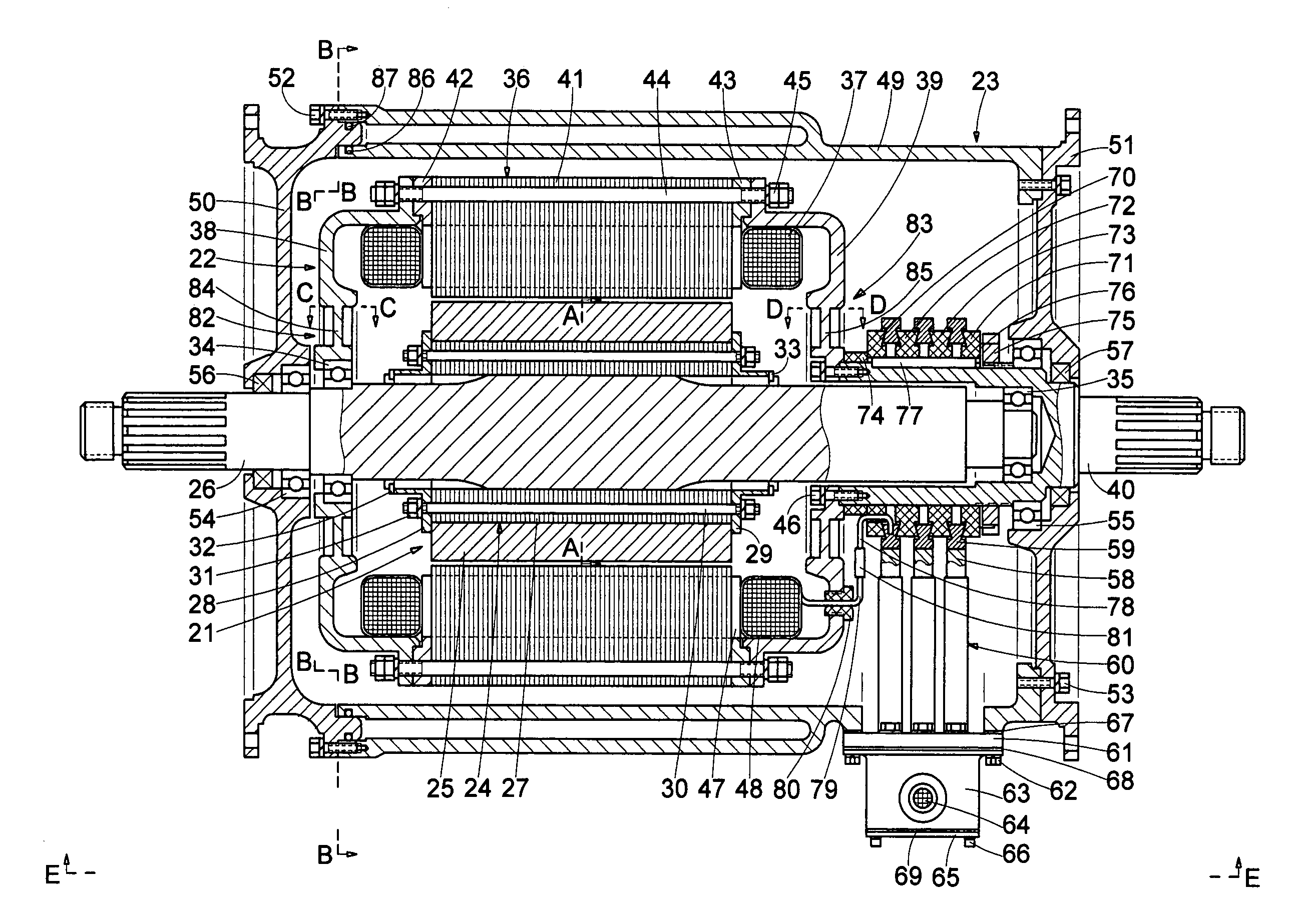
Figure 1 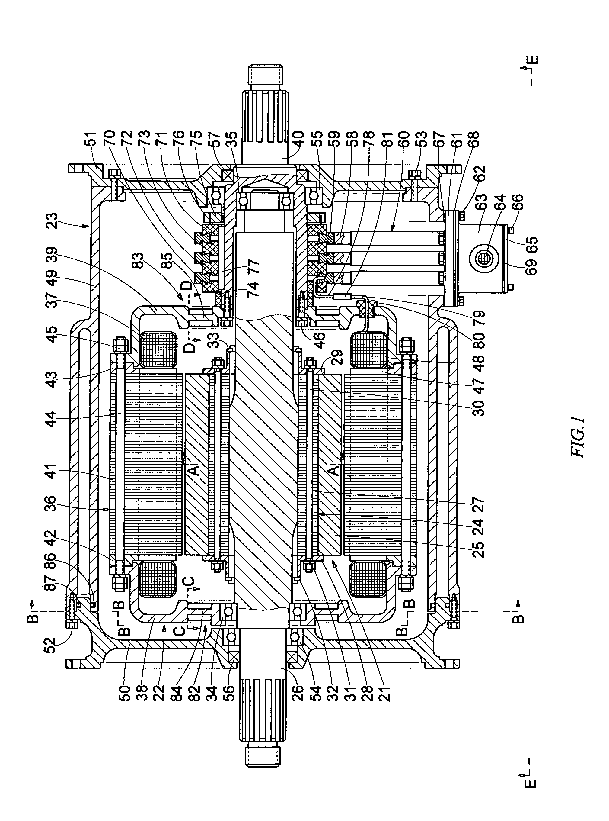
Figure 2 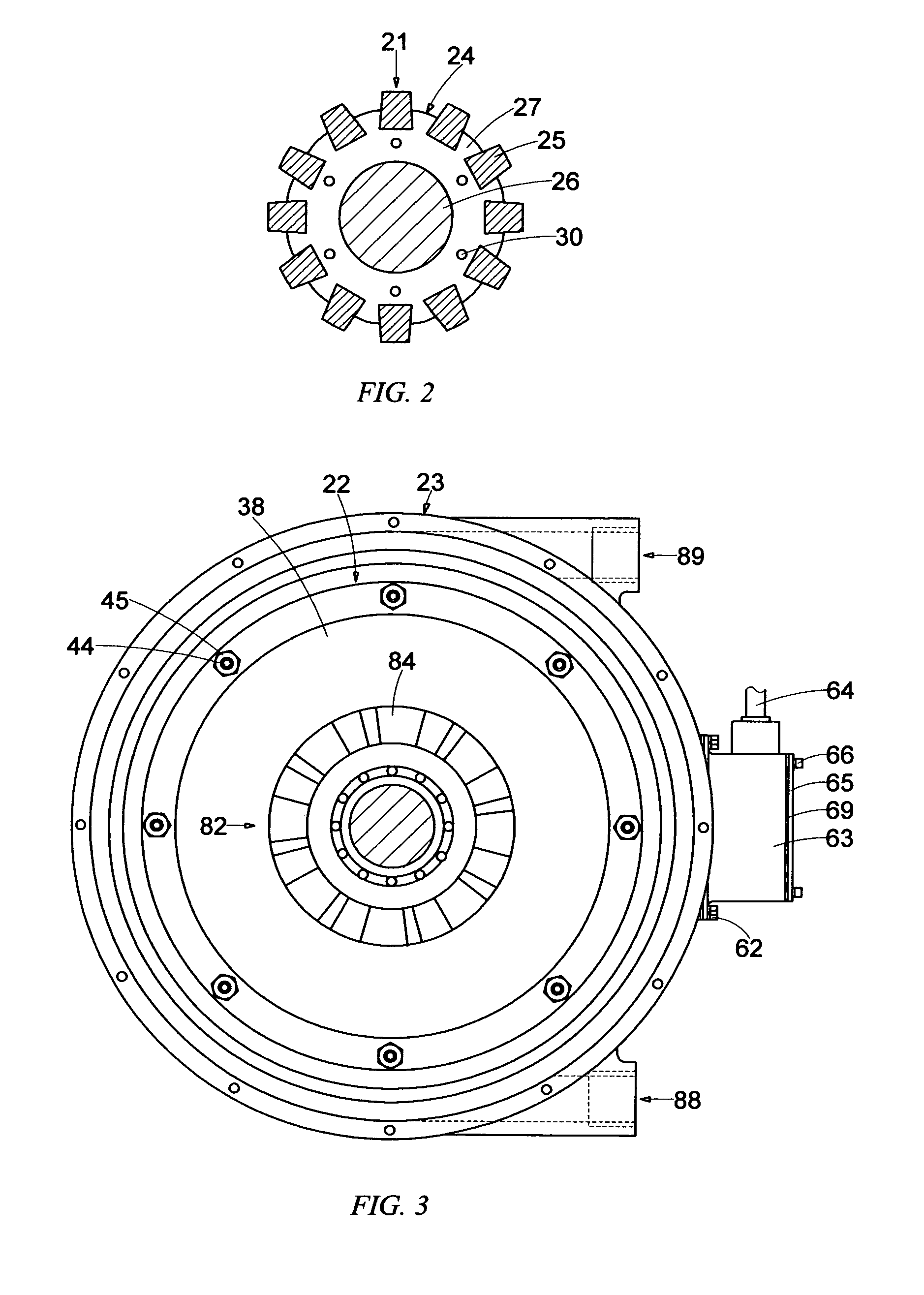
Figure 3
Abstract
Description
FIELD OF THE INVENTION
[0001] This invention relates generally to electric machines having two rotors and no stator, and more particularly to dual-rotor electric traction motors.BACKGROUND OF THE INVENTION
[0002] The conventional electric machines—motors and generators—consist of a stationary component (the stator) and a rotating component (the rotor). One of these components is arranged to operate as the field and the other—as the armature of the electric machine. When a conventional electric motor is energized and electric current flows through its windings, the interaction between the electromagnetic forces of the field and armature propels the rotor to rotate and generates mechanical energy. When the rotor of a conventional electric generator rotates, driven by external mechanical forces, a magnetic field rotating in relation to the armature windings cuts through the armature windings and produces voltage at the output terminals of the generator.
[0003] Dual-rotor electric motors, tho...
Examples
first embodiment
[0085]In this first embodiment, an external liquid-cooling system cools the motor enclosure 23. Usually, a motor liquid-cooling system includes a radiator and a fan for cooling the hot liquid coolant coming from the motor, a pump for circulating the coolant between the motor enclosure and radiator, and a plurality of connecting lines. Since such liquid-cooling systems are well known in the art, and for simplicity of drawings and description, the entire external cooling system is not shown, but only an arrangement of the motor enclosure for liquid cooling is illustrated and described.
[0086]Referring to FIG. 1, FIG. 3, and FIG. 6, in this embodiment, a part of the central cylindrical enclosure 49 has a double wall forming a substantially cylindrical cavity, in which the liquid coolant can flow. The first motor enclosure side flange 50, closes this cylindrical cavity, and two O-rings 86, 87 seal between the cylindrical enclosure and the first motor enclosure side flange.
[0087]An inlet ...
second embodiment
[0115]As it was mentioned earlier in this specification, the axial motion of the air, produced by the rotation of the fans, and the rotational motion of the air, produced by the rotation of the rotors, combine in a complicated spiral-like turbulent internal air circulation. Nevertheless, this complicated spiral-like air circulation will generally follow the close-loop lines shown in FIG. 22 or FIG. 23, depending on the opposite directions of rotation of the rotors. Although the dual-rotor motor is shown in these two figures, it shall be understood that this is only for purpose of illustration, and that the internal close-loop air circulation in all but one of the described in this specification embodiments of the dual-rotor motor will be substantially the same as the internal close-loop air circulation shown and described here in FIG. 22 or FIG. 23, depending on the opposite directions of rotations of the rotors. The exception is the briefly described embodiment that includes only o...