
Ultrasonic waterjet apparatus
a waterjet and ultrasonic technology, applied in the direction of cleaning using liquids, combustion types, borehole/well accessories, etc., can solve the problems of increasing costs, nozzles, water lines and fittings are bulky, and the effect of increasing the capacity of the apparatus to clean, cut, deburr, and decoa
Patent Information
- Authority / Receiving Office
- US · United States
- Patent Type
- Patents(United States)
- Current Assignee / Owner
- Publication Date
- 2009-09-29
Smart Images
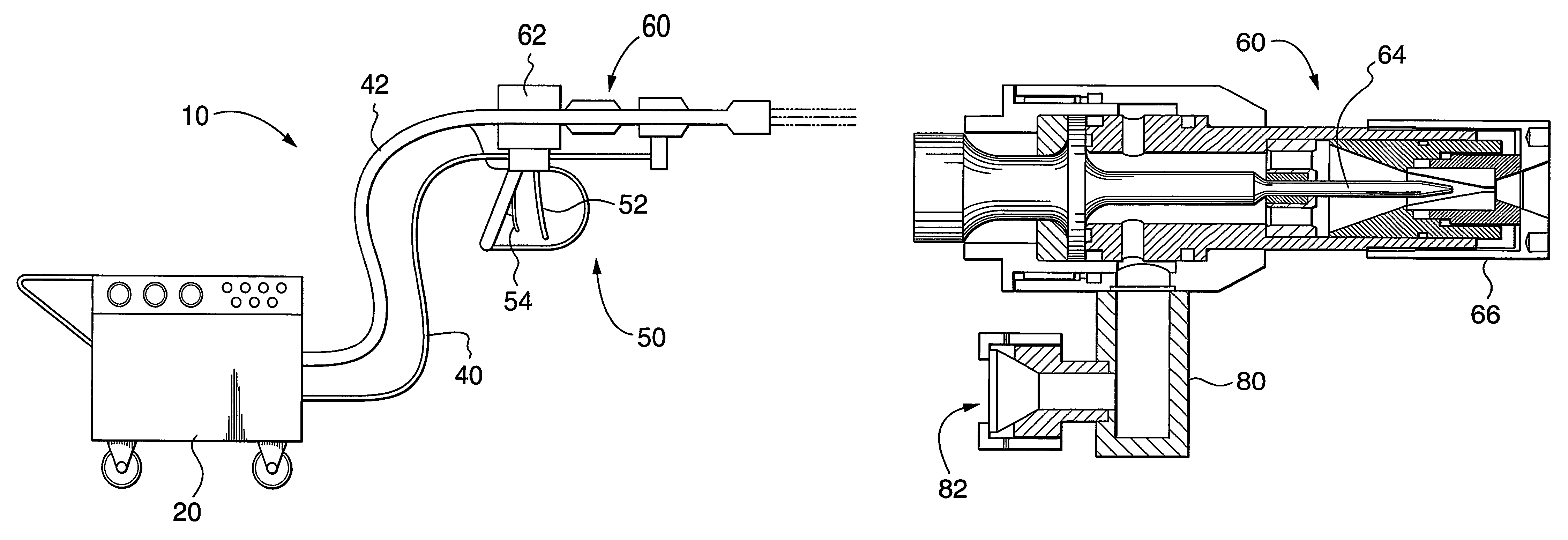
Figure 1 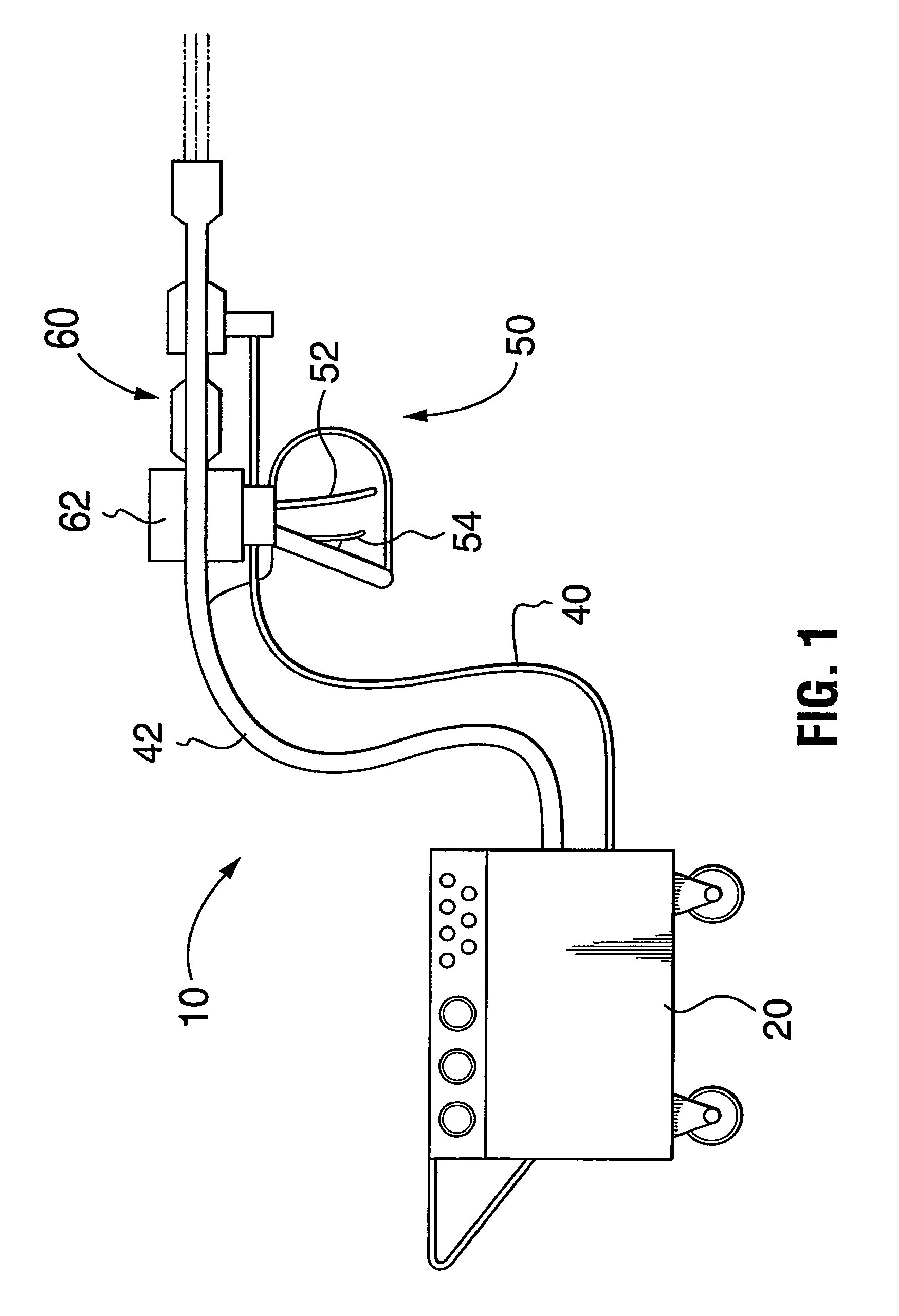
Figure 2 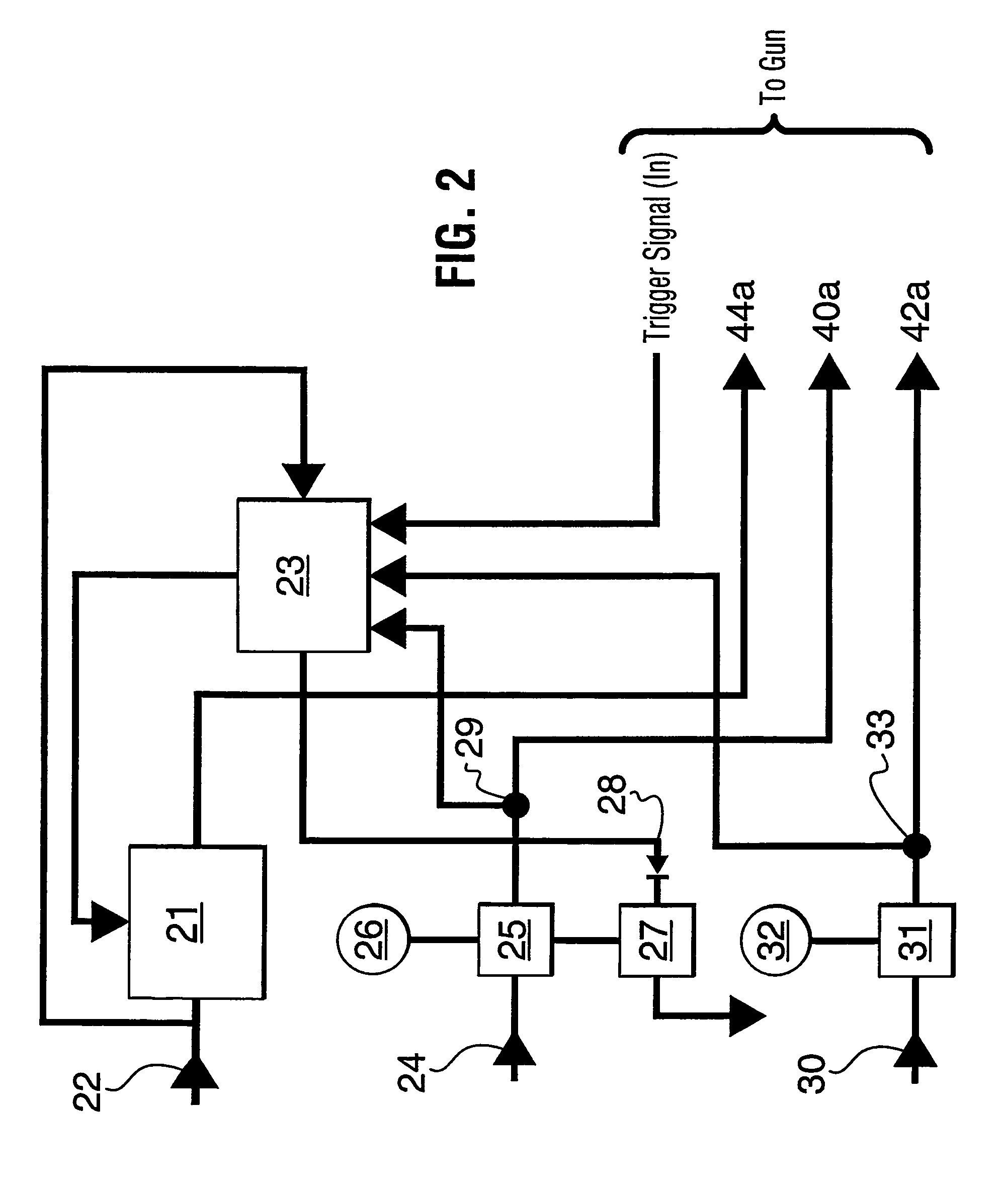
Figure 3
Abstract
Description
[0001] This application is a 35 U.S.C. 371 of PCT / CA03 / 01683 filed Nov. 3, 2003.TECHNICAL FIELD
[0002] The present invention relates, in general, to high-pressure waterjets for cleaning and cutting and, in particular, to high-frequency modulated waterjets.BACKGROUND OF THE INVENTION
[0003] Continuous-flow high-pressure waterjets are well known in the art for cleaning and cutting applications. Depending on the particular application, the water pressure required to produce a high-pressure waterjet may be in the order of a few thousand pounds per square inch (psi) for fairly straightforward cleaning tasks to tens of thousands of pounds per square inch for cutting and removing hardened coatings.
[0004] Examples of continuous-flow, high-pressure waterjet systems for cutting and cleaning are disclosed in U.S. Pat. Nos. 4,787,178 (Morgan et al.), 4,966,059 (Landeck), 6,533,640 (Nopwaskey et al.), 5,584,016 (Varghese et al.), 5,778,713 (Butler et al.), 6,021,699 (Caspar), 6,126,524 (Shepherd) and ...
Examples
second embodiment
[0059]As shown in FIG. 7, the ultrasonic nozzle 60 has a single orifice 61. A single orifice is useful for many applications such as cutting and deburring various materials as well as breaking rock-like materials. However, for applications such as cleaning or de-coating large surface areas, a single orifice only removes a narrow swath per pass. Therefore, for applications such as cleaning and removing coatings such as paint, enamel, or rust, it is useful to provide a second embodiment in which the ultrasonic nozzle has a plurality of orifices. An ultrasonic nozzle 60 with three orifices 61a is shown in FIG. 11. The microtip has three prongs for modulating the waterjet as it is forced through the three parallel exit orifices. The triple-orifice nozzle of FIG. 11 is thus able to clean or de-coat a wider swath than a single-orifice nozzle. As shown in FIG. 11, a nut 60a secures the multiple-orifice nozzle to a housing 60b. FIG. 11 shows how the microtip 64 culminates in three prongs 64...
third embodiment
[0060]In a third embodiment, which is illustrated in FIG. 12, the ultrasonic nozzle 60 has a rotating nozzle head 90 which permits the ultrasonic nozzle 60 to efficiently clean or de-coat a large surface area. The rotating nozzle head 90 is self-rotating because water is bled off into two outer jets 92. The bled-off water generates torque which causes the outer jets 92 to rotate, which, in turn, cause the rotating nozzle head 90 to rotate. In this embodiment, the bulk of the waterjet is forced through one or two angled exit orifices 91. Depending on the material to be cleaned, the outer jets may or may not contribute to the cleaning process. An acoustically matching swivel 94 is interposed between the transducer and the rotating nozzle head. The swivel 94 is designed to not only withstand the pressure but also acoustically match the rest of the system to achieve resonance. The swivel 94 may or may not have a speed control mechanism, such as a rotational damper, for limiting the angu...