
Extension attachment for a bulk material container
a technology for bulk materials and extension attachments, which is applied in the direction of containers, items transportation vehicles, tank vehicles, etc., can solve the problems of design height and appear to occur at the expense of carrying capacity, and achieve the effect of reducing the design height of extension attachments and reducing the inclination of flaps
Patent Information
- Authority / Receiving Office
- US · United States
- Patent Type
- Patents(United States)
- Current Assignee / Owner
- Publication Date
- 2011-04-05
- Estimated Expiration
- Not applicable · inactive patent
Smart Images
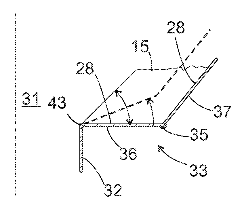
Figure 1 
Figure 2 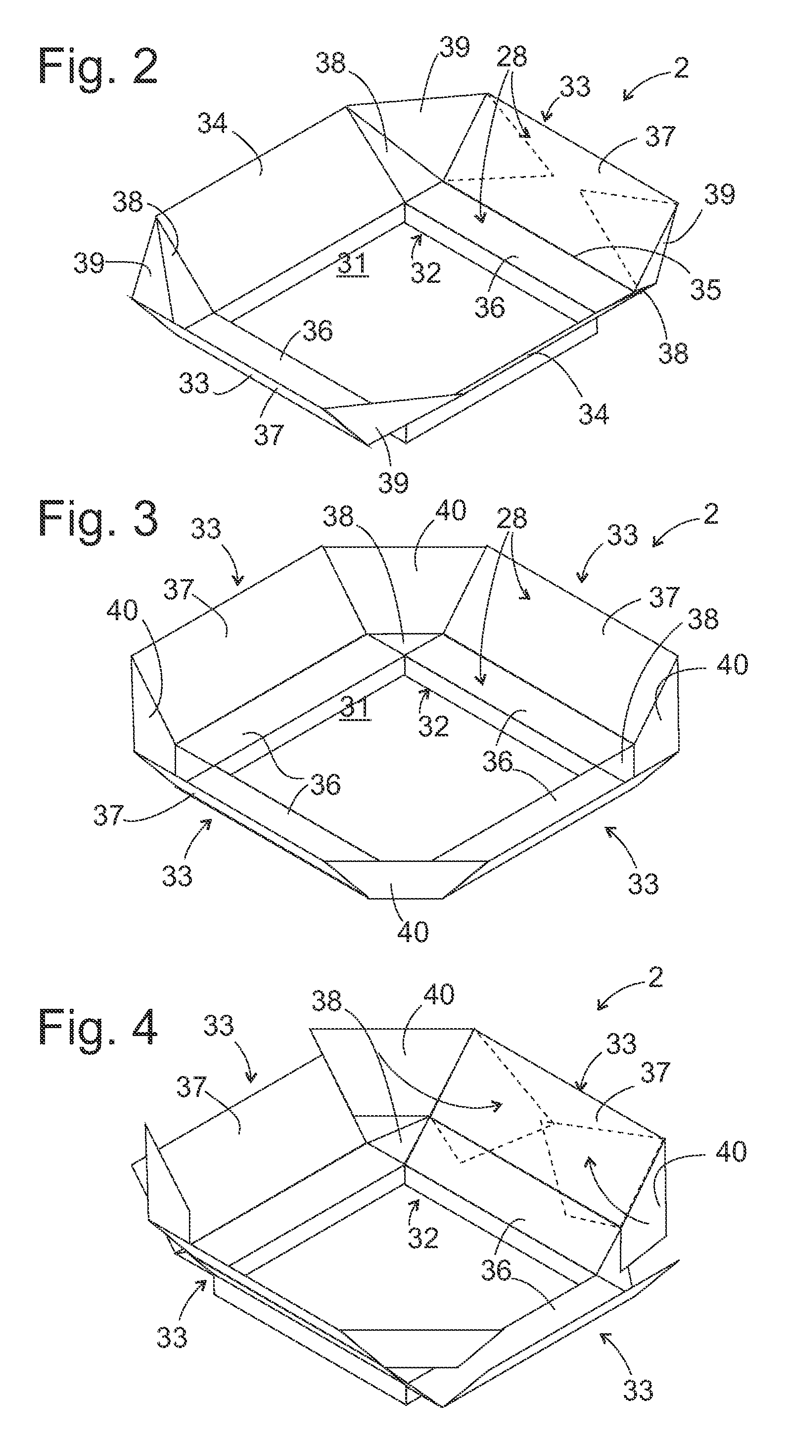
Figure 3
Abstract
Description
CROSS REFERENCE TO RELATED APPLICATIONS
[0001] This application claims benefit of priority to earlier filed German Patent Application 10 2007 003 653.3 filed in the German Patent Office on Jan. 18, 2007.FIELD OF THE INVENTION
[0002] The invention relates to an extension attachment for increasing the capacity of a bulk material container. In particular, it relates to a grain tank attachment for a combine harvester.BACKGROUND OF THE INVENTION
[0003] A grain tank of a combine harvester is frequently provided with an extension attachment that comprises several flaps pivotally linked to a frame to allow swiveling. Such a grain tank attachment is, for example, known from DE 10 2004 007 673 A1. When a combine harvester is travelling on the road, the flaps are swivelled inwards and lie flat on the opening of the grain tank so that the overall height of the combine harvester that is permissible on road traffic is not exceeded. During operation in the field, the flaps are in the swivelled-out posit...
Examples
first embodiment
[0030]FIG. 2 shows a perspective view of the extension attachment 2 according to the invention. A rectangular frame 32 comprising four vertical walls of the extension attachment can be an integral component of the grain tank 3 or can be attached on a top edge of the grain tank 3 and be fixed on it, i.e., an internal space 31 surrounded by the extension attachment 2 in lateral direction is open upwards and joins the grain tank 3 at the bottom—not depicted in FIG. 2.
[0031]At the top edge of each of the four walls of the frame 32 a flap 33, 33, 34, 34 is pivotally mounted. The flaps 34 are single-pieced, plane, rectangular or trapezoidal plates. The flaps 33 respectively consist of two segments connected pivotally with one another along a line 35, namely an inner segment 36 which is approximately horizontal in the swivelled-out position, and an outer segment 37. Since the two segments 36, 37 form an obtuse angle in cross-section on the line 35, a concave internal surface 28 (see also F...
second embodiment
[0036]the extension attachment according to the invention with four concave flaps 33 in a swivelled-out state is shown in FIG. 3. The triangular plates 38 located at the corners of frame 32 are connected by means of hinges on two of their edges with inner segments 36 of the two respective neighbouring flaps 33. Trapezoidal plates 40 respectively have an edge hinged with an outer segment 37, and two edges that touch in a grain-tight manner one of the triangular plates 38 and an adjoining outer segment 37, respectively.
[0037]This extension attachment 2 is foldable via an intermediate stage depicted in FIG. 4. Two inner segments 36 opposite one another are swivelled upwards about their edge that is linked to the frame 32 and inwards to a position which is coplanar to the outer segment 37 of the same flap 33. In this position, the trapezoidal plates 40 linked to the outer segments 37 are swivelled into a position outlined with dashed lines, in which they lie flat on the flaps 33 carryin...