
Exhaust gas system
a technology of exhaust gas and guidance elements, which is applied in the direction of hot gas positive displacement engine plants, machines/engines, mechanical equipment, etc., can solve the problems of putting a great load on the flange fastening and/or the exhaust gas guidance elements, and achieve the flow behavior of the exhaust gas
Patent Information
- Authority / Receiving Office
- US · United States
- Patent Type
- Patents(United States)
- Current Assignee / Owner
- Publication Date
- 2011-07-05
Smart Images
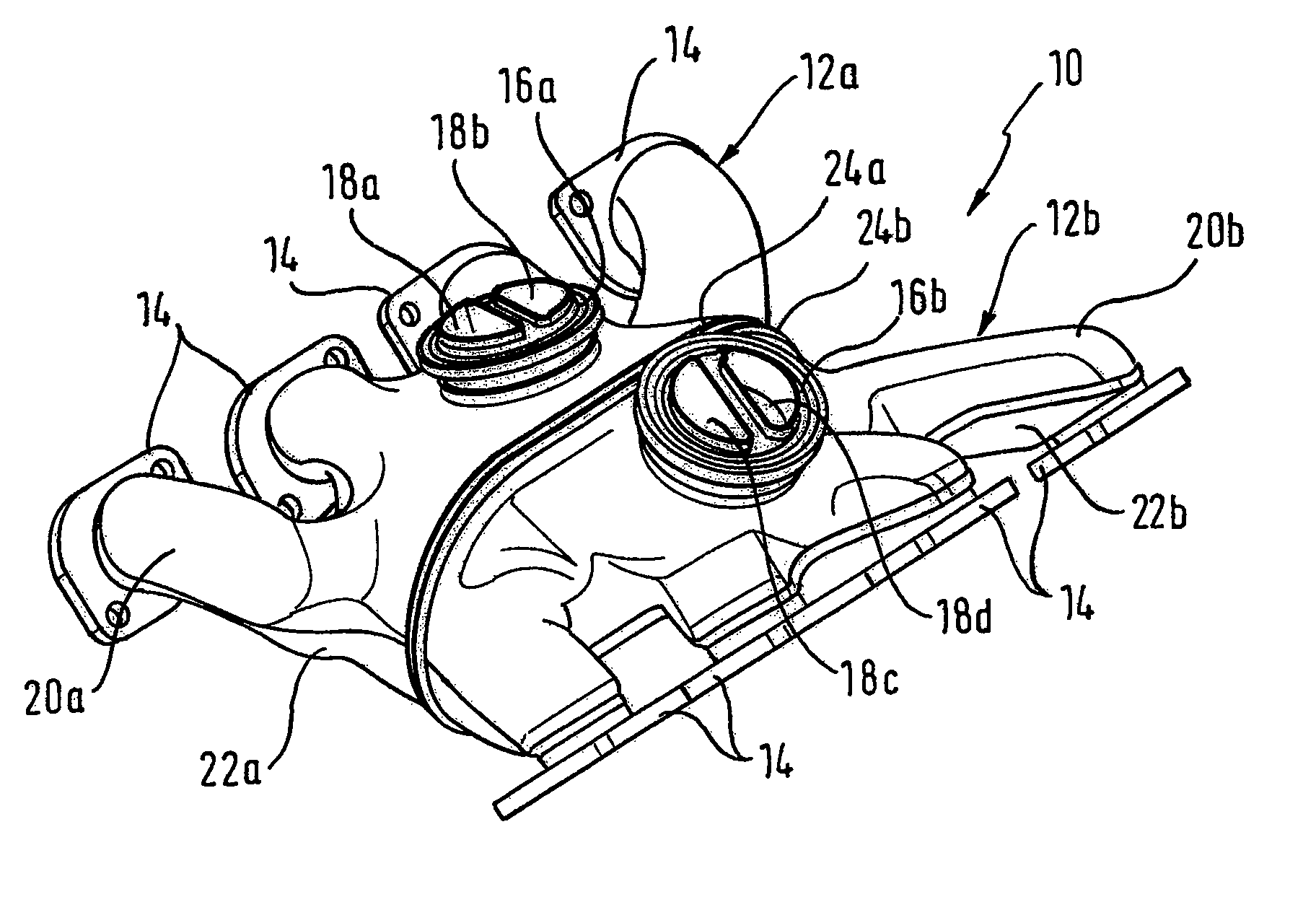
Figure 1 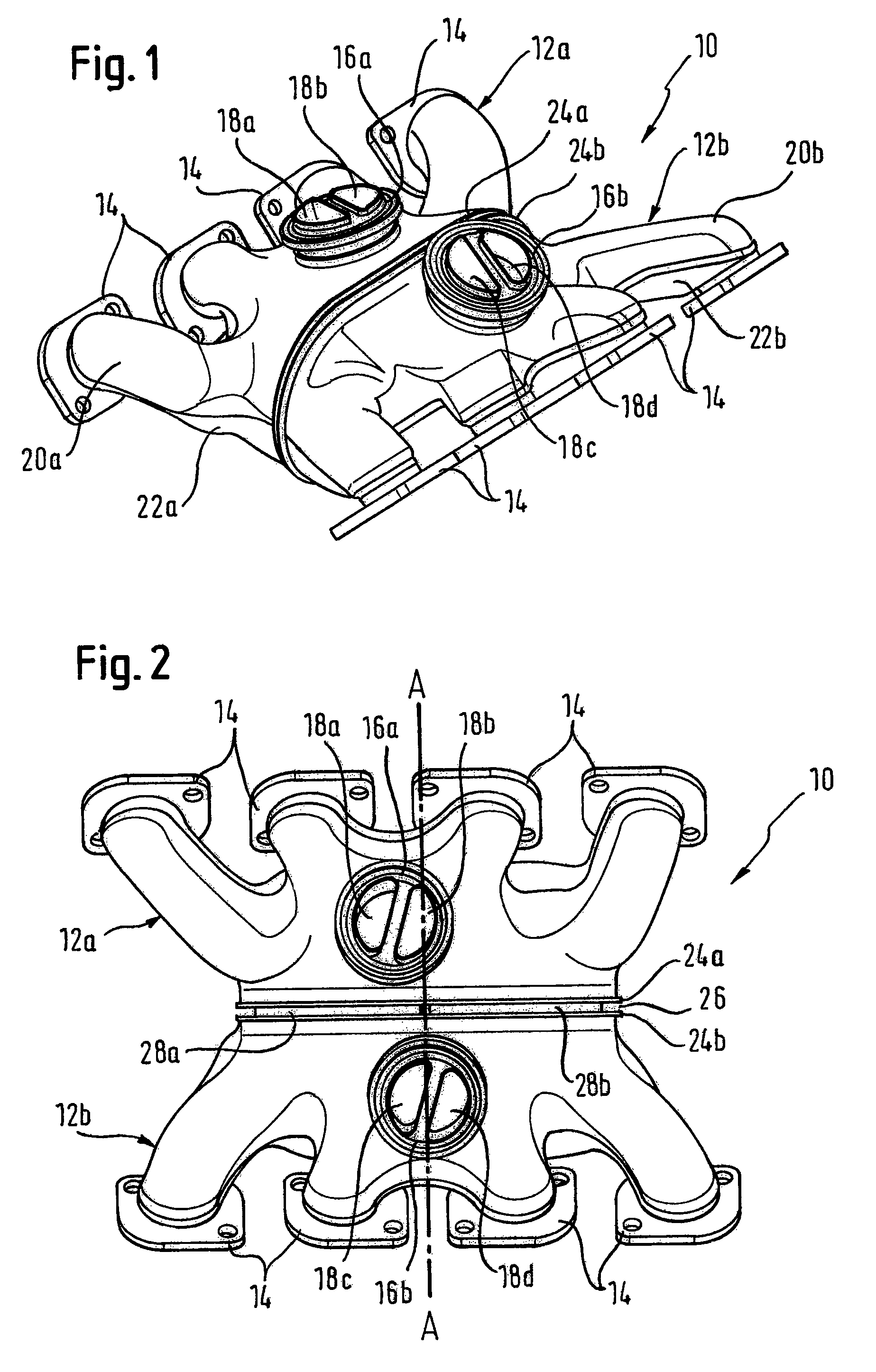
Figure 2 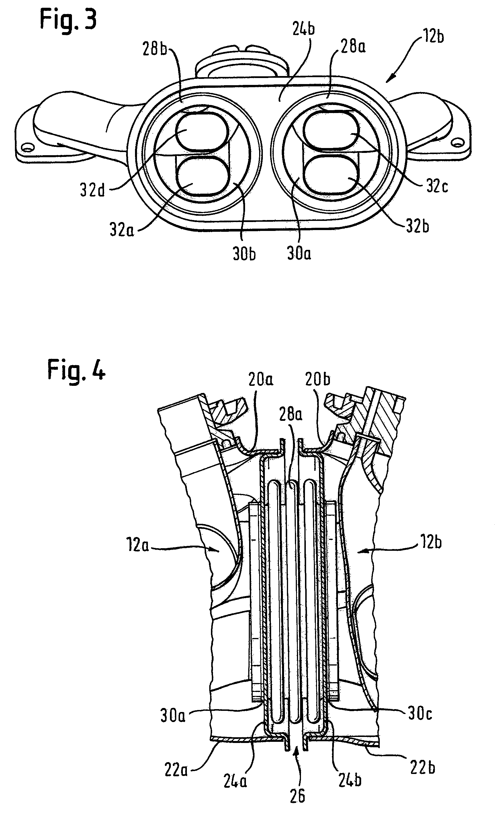
Figure 3
Abstract
Description
FIELD OF THE INVENTION
[0001] The present invention relates to an exhaust gas system for an internal combustion engine, in particular a motor vehicle engine, having two cylinder banks arranged at an acute angle to one anther and each having at least one exhaust gas outlet, a so-called V-engine, having exhaust gas guide elements arranged in the region of the inner angle, including a housing surrounding the exhaust gas outlets of both cylinder banks in a gas tight manner and having at least one exhaust gas outlet opening.BACKGROUND OF THE INVENTION
[0002] The exhaust gas system serves for the leading away of the hot combustion gases arising in the internal combustion engine and is flanged directly to the corresponding outlets of the internal combustion engine. The housing surrounds the outlets of both cylinder banks in a gas tight manner. A connection is thereby possible between the outlets of the one cylinder bank and the outlets of the other cylinder bank in order also to enable crossta...
Examples
Embodiment Construction
[0026]FIGS. 1 and 2 show a housing 10 of an exhaust gas system in accordance with the invention for an internal combustion engine which has two cylinder banks which are not shown here, which are arranged at an acute angle to one another and which each have four exhaust gas outlets. The housing 10 includes two housing parts 12a, 12b of which each one respectively includes four flanges 14 arranged in a row for the connection to the exhaust gas outlets of a cylinder bank. The two rows of flanges 14 accordingly face in opposite directions.
[0027]Each housing part 12a, 12b has an exhaust gas outlet opening 16a and 16b respectively which is provided for connection to following elements, not shown, of the exhaust gas system, for example to an exhaust gas turbocharger or to an exhaust gas purification system. Two exhaust gas collection devices 18a, 18b and 18c, 18c respectively, which are arranged mainly in the interior of the housing parts 12a, 12b and which are in turn connected to exhaust...