
Oil pressure control device
a technology of oil pressure control and control device, which is applied in the direction of water supply installation, machine/engine, drawing-off water installation, etc., can solve the problems of destabilization of line pressure, deformation of line pressure, and inability of valves and the like to operate normally, so as to achieve accurate oil pressure control
Patent Information
- Authority / Receiving Office
- US · United States
- Patent Type
- Patents(United States)
- Current Assignee / Owner
- Publication Date
- 2013-03-12
- Estimated Expiration
- Not applicable · inactive patent
Smart Images
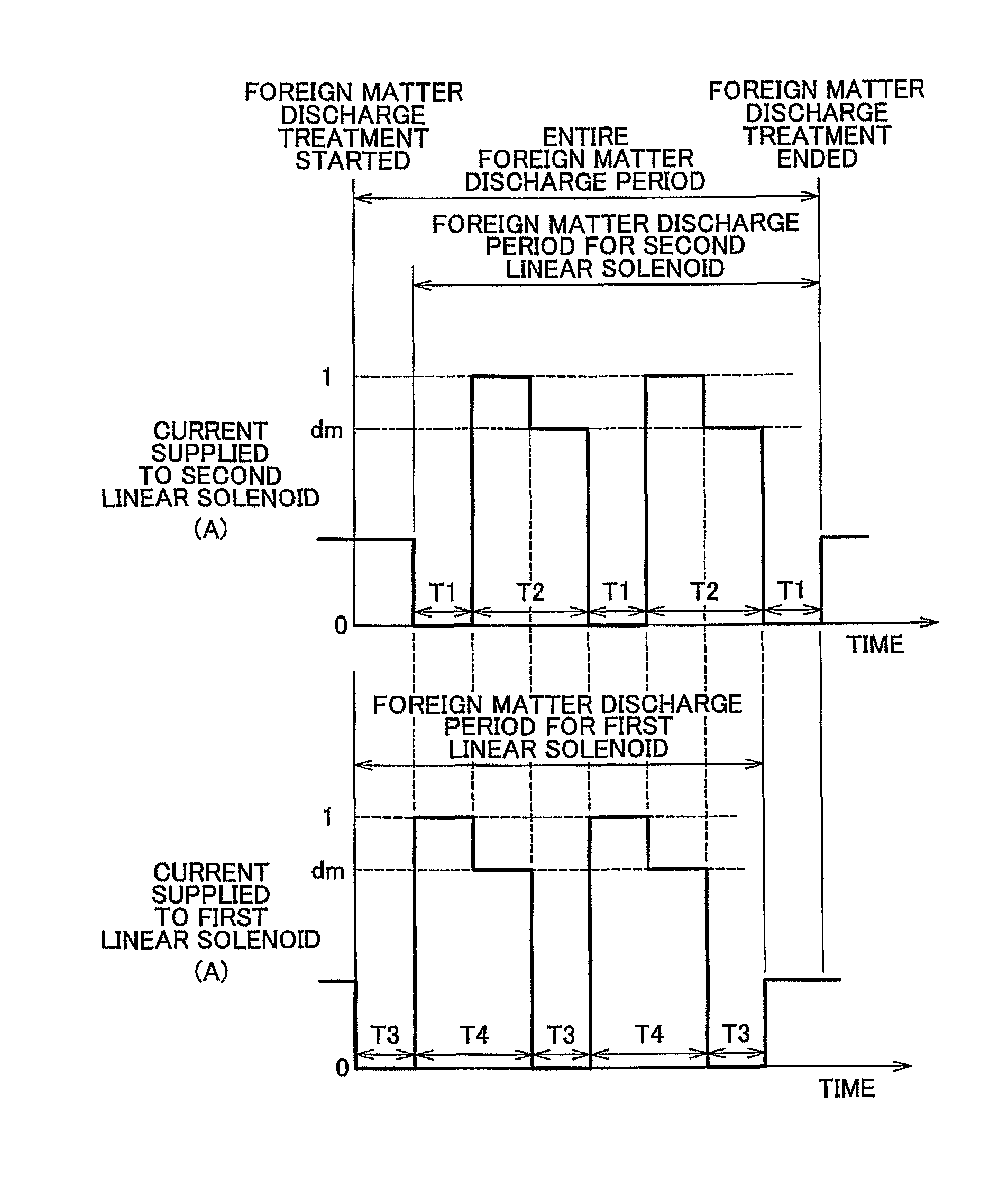
Figure 1 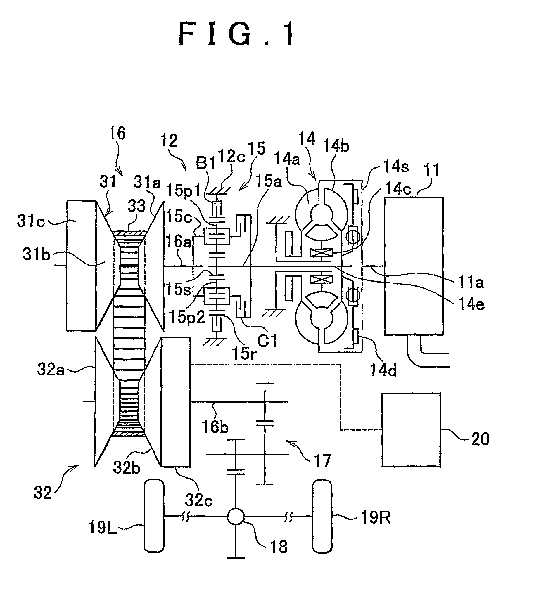
Figure 2 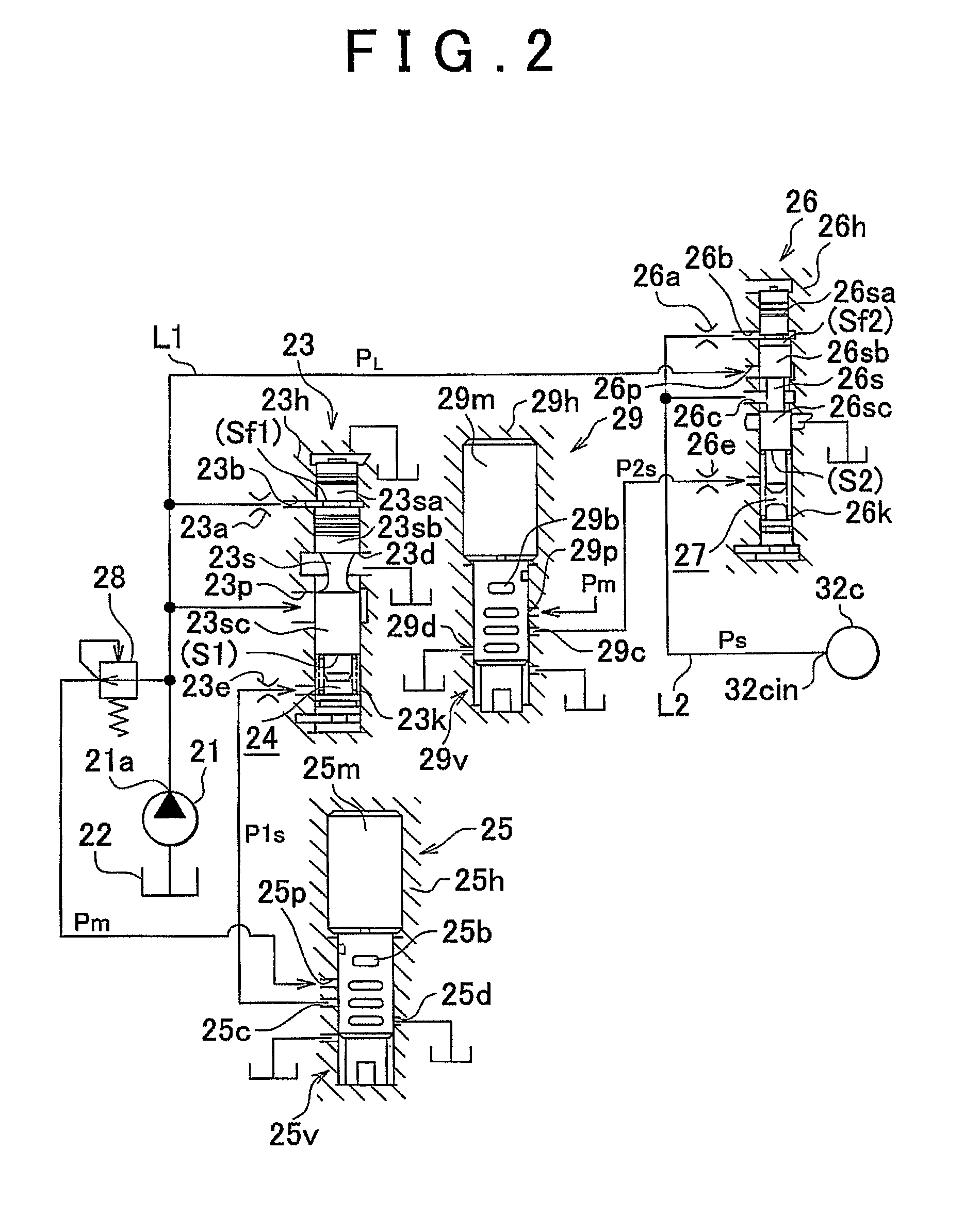
Figure 3
Abstract
Description
BACKGROUND OF THE INVENTION
[0001] 1. Field of the Invention
[0002] The invention relates to an oil pressure control device that carries out a treatment of discharging foreign matters that have mingled in a circuit, and more particularly, to an oil pressure control device for carrying out a foreign matter discharge treatment for a plurality of solenoid valves.
[0003] 2. Description of the Related Art
[0004] In each of various oil pressure control circuits, a solenoid valve such as an electromagnetic proportional control valve or the like, which operates a valve body with the aid of a solenoid in order to control the pressure of a working fluid for actuating a group of actuators, is employed. The pressure and flow rate of the working fluid that are required for actuation of the actuators are ensured by, for example, operating another control valve using an output pressure of the solenoid valve as a pilot pressure. When foreign matters mingle in an oil pressure control circuit, the valves and...
Examples
first embodiment
[0032]FIGS. 1 to 6 are views showing the first embodiment of an oil pressure control device according to the invention. These figures show an example in which the invention is applied to an oil pressure control device for controlling the pressure of a working fluid in a belt-type continuously variable transmission for an automobile.
[0033]First of all, the configuration of the oil pressure control device will be described. As shown in FIG. 1 as a skeleton diagram of a power transmission path of the automobile, a vehicle (the automobile not entirely shown) according to this embodiment of the invention is mounted with an engine 11 as a prime mover, and a transmission 12 capable of changing the speed of the rotational output of this engine 11. The transmission 12 includes a torque converter 14, a forward / backward changeover gear mechanism 15, a belt-type continuously variable shift mechanism 16, and an oil pressure control portion 20. A power transmission path is set such that an output...
second embodiment
[0081]FIG. 7 is a view showing another embodiment of an oil pressure control device according to the invention. This embodiment of the invention is different from the first embodiment of the invention in means for performing foreign matter discharge control upon fulfillment of the foreign matter discharge condition and the contents of the foreign matter discharge treatment, but identical to the foregoing embodiment of the invention in other configurational details and the foreign matter discharge condition itself. In this case, therefore, the following description will focus especially on what is different from the foregoing embodiment of the invention, using the symbols shown in FIGS. 1 to 6 for the same component elements as in the foregoing embodiment of the invention.
[0082]As shown in FIG. 7, in this embodiment of the invention, the current values of the currents supplied to the two linear solenoid valves 25 and 29 in the period of the simultaneous foreign matter discharge treat...