
Engine that is equipped with variable valve device
a variable valve and valve device technology, applied in the field of engines, can solve the problems of difficult to simply or compactly constitute the variable valve train and the hydraulic pressure lash adjuster in a restricted space, and achieve the effect of reducing the weight of components and small overall structur
Patent Information
- Authority / Receiving Office
- US · United States
- Patent Type
- Patents(United States)
- Current Assignee / Owner
- Publication Date
- 2014-02-04
- Estimated Expiration
- Not applicable · inactive patent
Smart Images
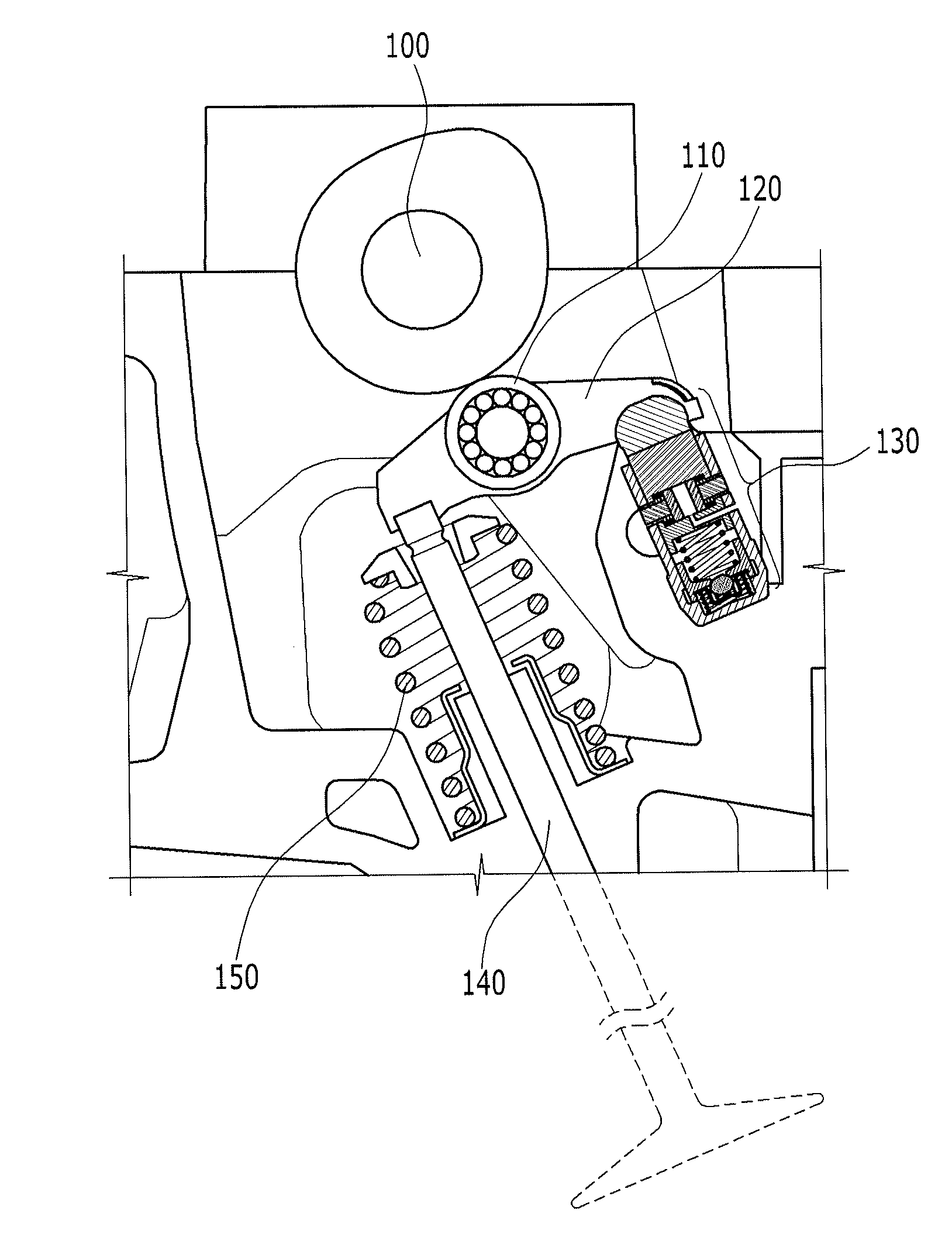
Figure 1 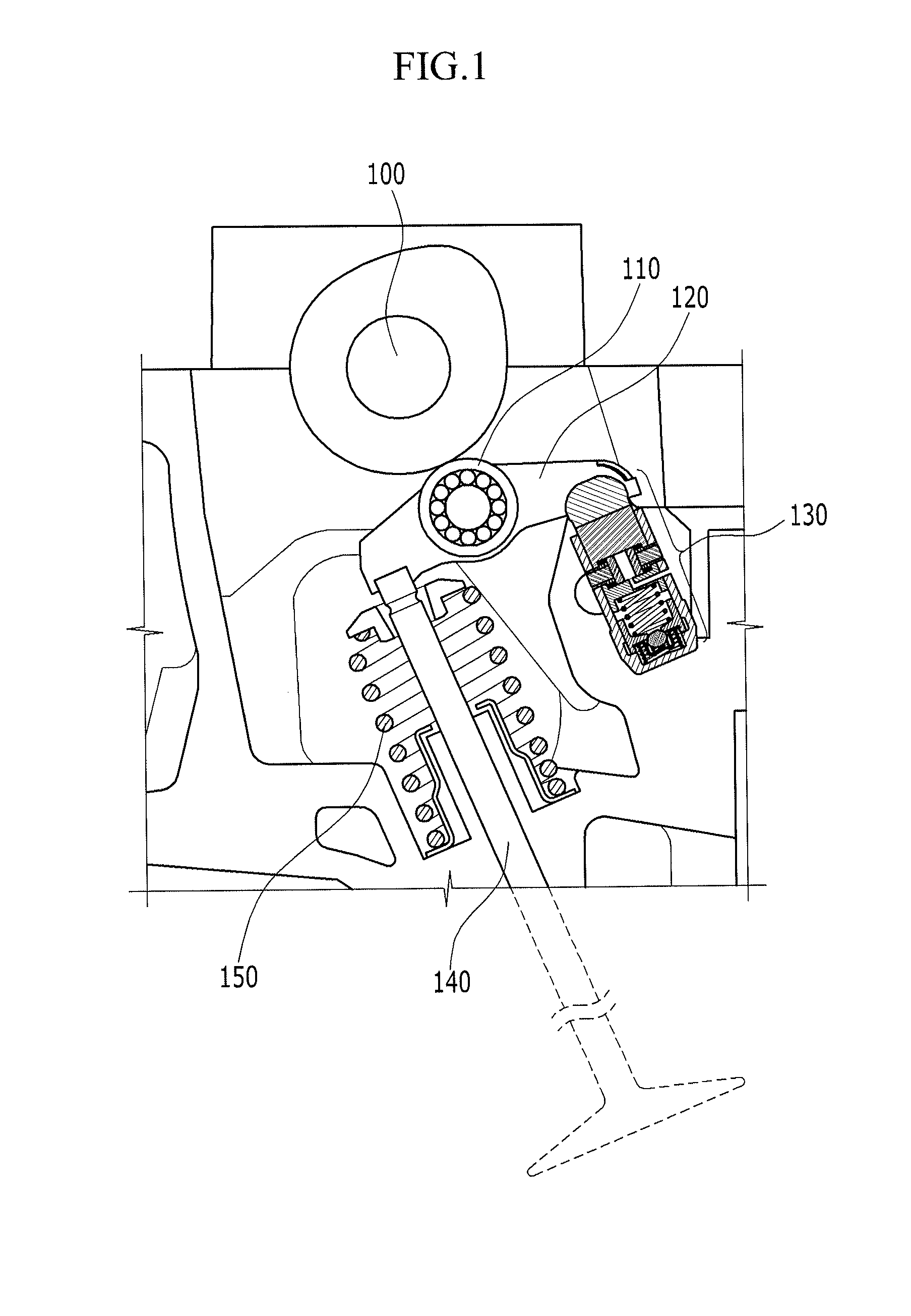
Figure 2 
Figure 3
Abstract
Description
CROSS-REFERENCE TO RELATED APPLICATION
[0001] The present application claims priority to Korean Patent Application No. 10-2010-0092697 filed in the Korean Intellectual Property Office Sep. 20, 2010, the entire contents of which is incorporated herein for all purposes by this reference.BACKGROUND OF THE INVENTION
[0002] 1. Field of the Invention
[0003] The present invention relates to an engine that is provided with a variable valve device that variably controls a motion of a valve disposed at an intake port or an exhaust port of a combustion chamber so as to improve fuel efficiency.
[0004] 2. Description of Related Art
[0005] Some means for varying the timing of valve actuation of internal combustion engines are very well known. Such means typically take the form of a camshaft, a rocker arm, or a finger follower so as to control the valve motion.
[0006] A variable valve device is especially well known in spark ignited engines, in which it is an essential element of various schemes for improving...
Examples
Embodiment Construction
[0023]Reference will now be made in detail to various embodiments of the present invention(s), examples of which are illustrated in the accompanying drawings and described below. While the invention(s) will be described in conjunction with exemplary embodiments, it will be understood that present description is not intended to limit the invention(s) to those exemplary embodiments. On the contrary, the invention(s) is / are intended to cover not only the exemplary embodiments, but also various alternatives, modifications, equivalents and other embodiments, which may be included within the spirit and scope of the invention as defined by the appended claims.
[0024]An exemplary embodiment of the present invention will hereinafter be described in detail with reference to the accompanying drawings.
[0025]FIG. 1 is a schematic cross-sectional view of an engine that is provided with a variable valve device according to an exemplary embodiment of the present invention.
[0026]Referring to FIG. 1, ...