
Variable filter circuit and wireless communication apparatus
a filter circuit and filter circuit technology, applied in the field of variable filter circuit and wireless communication apparatus, can solve the problems of increasing circuit size and complication of control system, difficult to obtain steep filter characteristics near the high-frequency side of the pass band, and difficulty in obtaining desired attenuation characteristics, etc., to suppress significant degradation of filter characteristics, reduce circuit size, and narrow the range of variation of cutoff frequency
Patent Information
- Authority / Receiving Office
- US · United States
- Patent Type
- Patents(United States)
- Current Assignee / Owner
- Publication Date
- 2017-10-03
Smart Images
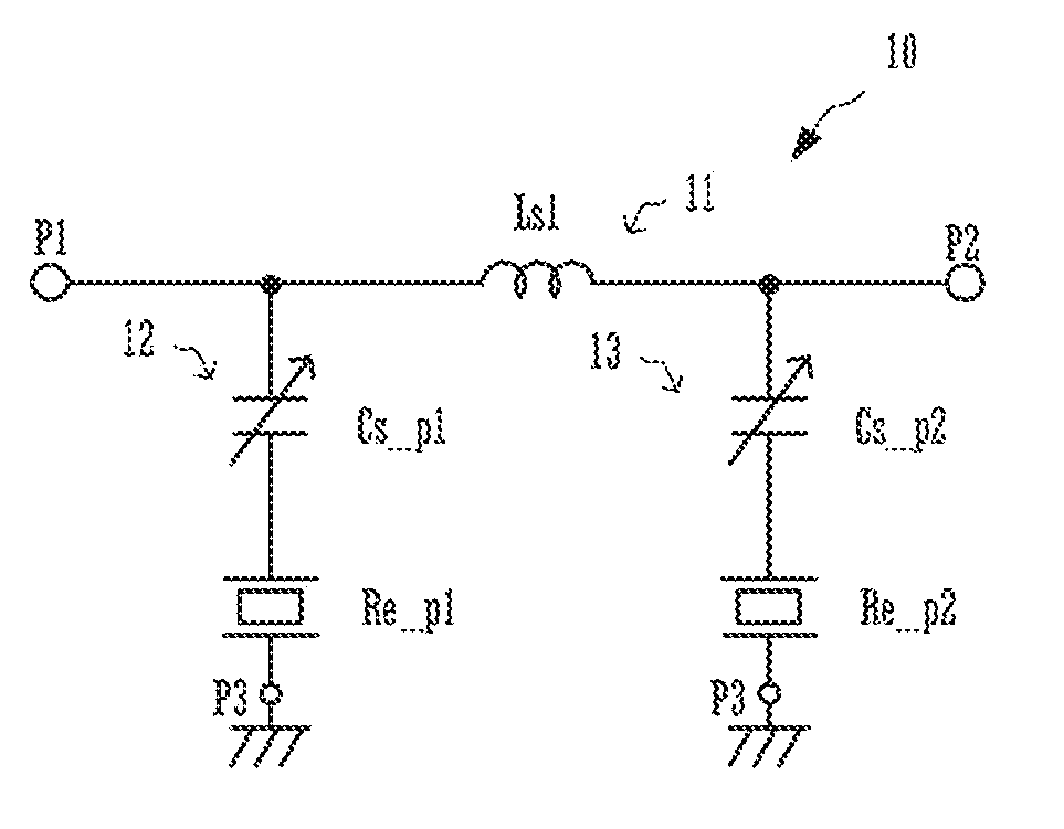
Figure 1 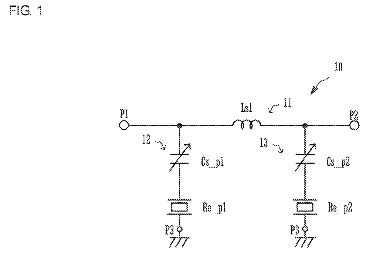
Figure 2 
Figure 3
Abstract
Description
[0001] This application is a continuation of International Application No. PCT / JP2015 / 053171 filed on Feb. 5, 2015 which claims priority from Japanese Patent Application No. JP2014-202078 filed on Sep. 30, 2014 and Japanese Patent Application No. JP2014-023341 filed on Feb. 10, 2014. The contents of these applications are incorporated herein by reference in their entireties.BACKGROUNDTechnical Field
[0002] The present disclosure relates to a variable filter circuit and a wireless communication apparatus including the variable filter circuit.
[0003] Conventional variable filter circuits have been given ladder configurations, in which basic circuits are configured by connecting variable capacitances in parallel or in series to resonators such as SAW resonators or BAW resonators and such basic circuits are then combined in multiple stages (see Patent Document 1, for example). In the variable filter circuit, an anti-resonant frequency of each basic circuit is adjusted by controlling the vari...
Examples
first embodiment
[0043]FIG. 1 is a circuit diagram illustrating a variable filter circuit 10 according to a first embodiment of the present disclosure.
[0044]The variable filter circuit 10 includes ports P1, P2, and P3, a serial arm 11, and parallel arms 12 and 13. The port P1 is a first input / output end of the variable filter circuit 10. The port P2 is a second input / output end of the variable filter circuit 10. The port P3 is a ground connection end of the variable filter circuit 10. The serial arm 11 is connected in series between the port P1 and the port P2. The parallel arm 12 is connected in series between the port P1 and the port P3. The parallel arm 13 is connected in series between the port P2 and the port P3.
[0045]The serial arm 11 includes a first inductor Ls1. The first inductor Ls1 is provided between the port P1 and the port P2, with one end thereof connected to one end of the parallel arm 12 and another end thereof connected to one end of the parallel arm 13. The parallel arm 12 includ...
second embodiment
[0060]FIG. 4 is a circuit diagram illustrating a variable filter circuit 10A according to a second embodiment.
[0061]The variable filter circuit 10A has almost the same configuration as in the above-described first embodiment, but the parallel arms 12 and 13 include serial inductors (second inductors) Ls_p1 and Ls_p2 in addition to the resonators Re_p1 and Re_p2 and the variable capacitances Cs_p1 and Cs_p2. The serial inductor Ls_p1 is connected in series between the resonator Re_p1 and the variable capacitance Cs_p1. The serial inductor Ls_p2 is connected in series between the resonator Re_p2 and the variable capacitance Cs_p2.
[0062]The following descriptions assume that the serial inductors Ls_p1 and Ls_p2 are both at fixed inductances of approximately 50 nH. Aside from this, the resonators Re_p1 and Re_p2, the variable capacitances Cs_p1 and Cs_p2, the first inductor Ls1, and so on are assumed to have the same element values as in the first embodiment.
[0063]FIG. 5A is an impedanc...
third embodiment
[0079]FIG. 8 is a circuit diagram illustrating a variable filter circuit 10B according to a third embodiment.
[0080]The variable filter circuit 10B has almost the same configuration as in the above-described second embodiment, but the parallel arms 12 and 13 include parallel inductors (third inductors) Lp_p1 and Lp_p2 in addition to the resonators Re_p1 and Re_p2, the serial inductors Ls_p1 and Ls_p2, and the variable capacitances Cs_p1 and Cs_p2. The parallel inductor Lp_p1 is connected in parallel to the resonator Re_p1, with one end thereof being connected to a connection point between the serial inductor Ls_p1 and the resonator Re_p1 and another end thereof being connected to the port P3. The parallel inductor Lp_p2 is connected in parallel to the resonator Re_p2, with one end thereof being connected to a connection point between the serial inductor Ls_p2 and the resonator Re_p2 and another end thereof being connected to the port P3.
[0081]The following descriptions assume that th...