
Tidal current meter
a technology meter, which is applied in the field of tide current meter, can solve the problems of inability to properly measure the doppler shift frequency, difficult to measure the tidal current at a shallow place, and difficulty in measuring the velocity of a tidal current at a small depth, so as to avoid a decrease in frequency resolution, increase the time interval, and the effect of pulse width
Patent Information
- Authority / Receiving Office
- US · United States
- Patent Type
- Patents(United States)
- Current Assignee / Owner
- Publication Date
- 2018-03-13
Smart Images
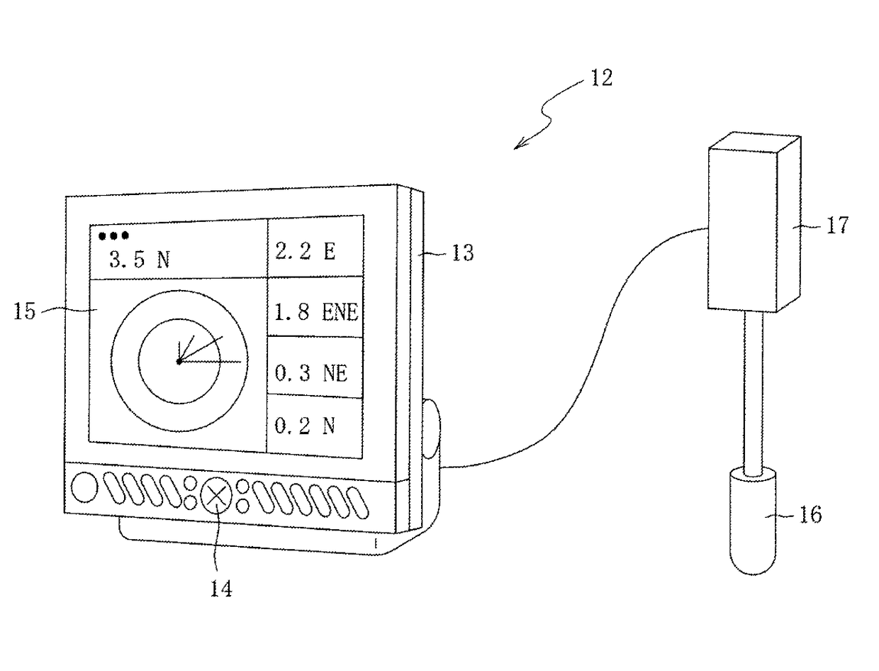
Figure 1 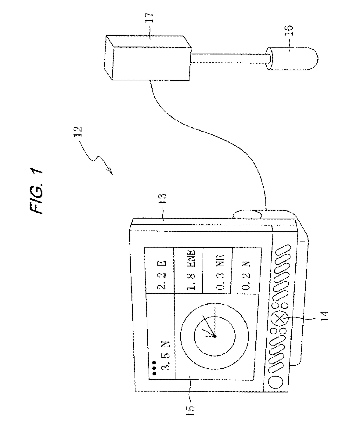
Figure 2 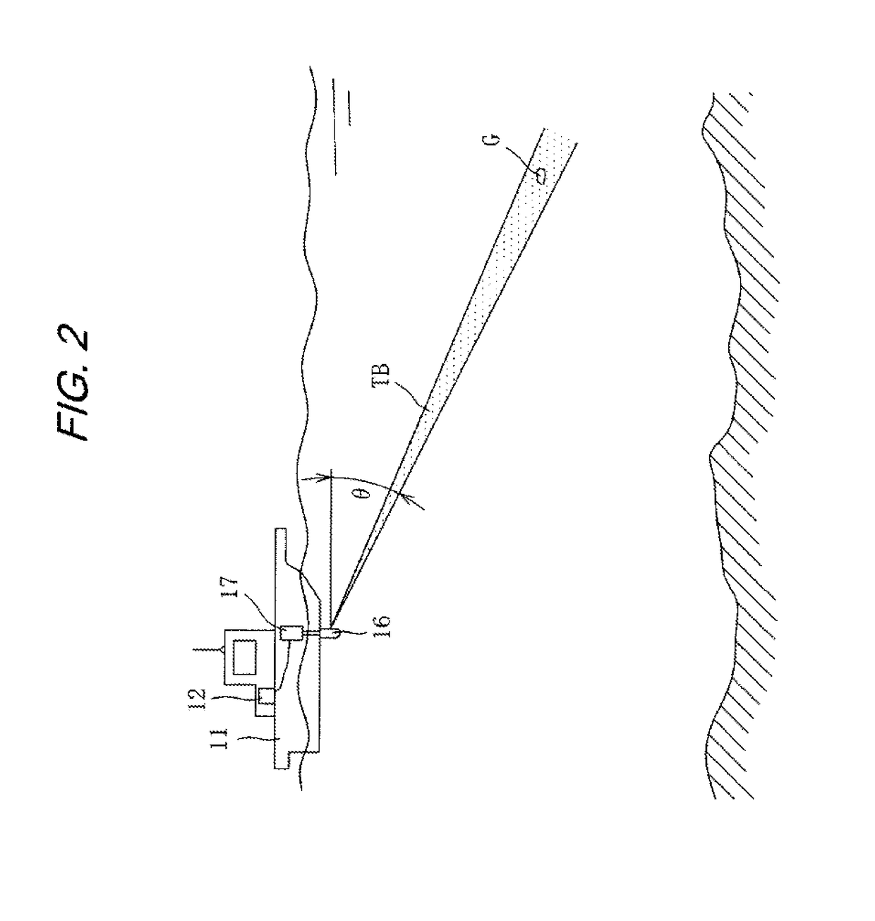
Figure 3
Abstract
Description
BACKGROUND OF THE INVENTION
[0001] (1) Field of the Invention
[0002] The present invention relates to a tidal current meter that measures the velocity of a tidal current at a predetermined depth of water such as the ocean or a lake.
[0003] (2) Description of the Related Art
[0004] A well-known tidal current meter described, for instance, in Japanese Unexamined Patent Application Publication No. 2011-203276 transmits an ultrasonic wave into water, receives a wave reflected, for example, from clutter, and measures the velocity of a tidal current at a predetermined depth in the water in accordance with the Doppler shift frequency of the reflected wave.
[0005] A conventional tidal current meter is configured so that three oscillators are mounted, for example, on the bottom of a ship and positioned 120 degrees apart from each other when the surface of water is viewed from above. The tidal current meter is configured so that the three oscillators transmit an ultrasonic wave in directions 120 degree...
Examples
first embodiment
[0025]Embodiments of the present invention will now be described with reference to the accompanying drawings. First of all, a tidal current meter 12 according to the present invention will be outlined with reference to FIGS. 1 to 3. FIG. 1 is a schematic diagram illustrating an outline configuration of the tidal current meter 12. FIG. 2 is a schematic side view illustrating how the velocity of a tidal current in water is measured by a ship 11 on which the tidal current meter 12 is mounted. FIG. 3 is a schematic perspective view illustrating the measurement of the velocity of the tidal current in water.
[0026]The tidal current meter 12 is mounted in a ship 11 as illustrated in FIGS. 1 to 3 to measure the velocity (speed and direction) of a tidal current around the ship 11 at a user-selected depth of water. The tidal current meter 12 is configured to accurately measure the velocity of a tidal current not only at a deep place but also at a shallow place. The tidal current meter 12 is ca...
second embodiment
[0101]The tidal current meter 12 includes a depth gauge (not shown). In the tidal current measurement process performed by the CPU 11, the depth gauge measures the depth of water h directly below the ship 11.
[0102]The depth gauge need not always be attached to the tidal current meter 12. The tidal current meter 12 may alternatively be configured so as to obtain an input of the water depth h measured by an externally disposed depth gauge. Another alternative is to use the wave transmission / reception unit 16 of the tidal current meter 12 to transmit the ultrasonic beam TB in a vertical direction from the ship 11 (at a depression angle θ of 90 degrees) and receive a wave reflected from a bottom such as the ocean floor or lake bed for the purpose of measuring the water depth h directly below the ship 11.
[0103]Here, if the ultrasonic beam TB is transmitted in a vertical direction (in a direction at a depression angle θ of 90 degrees) from the ship 11, a wave reflected from clutter G is ...
third embodiment
[0110]When the user operates the operating button 14, the tidal current meter 12 selects an analysis depth targeted for tidal current measurement and sets the depression angle θ of the ultrasonic beam TB for measuring at the selected analysis depth. More specifically, when the user selects an analysis depth, the display device 15 opens a screen that prompts for the input of the depression angle θ of the ultrasonic beam TB in accordance with the selected analysis depth.
[0111]In response to a prompt displayed on the screen, the user enters the depression angle θ of the ultrasonic beam TB by using the operating button 14. Data indicative of the entered depression angle θ is then stored in the RAM 53. If a plurality of analysis depths are selected, the depression angle θ of the ultrasonic beam TB can be set for each selected analysis depth. After the depression angle θ of the ultrasonic beam TB is set, the user may be allowed to change the depression angle θ by operating the operating ...