
Production of ammonium species
The method of using a nitrogen plasma to form ammonia and ammonium species in a solvent at low temperatures and atmospheric pressure addresses the energy and emissions issues of the Haber-Bosch process, enabling efficient and decentralized production of nitrogenous fertilizers like urea.
Patent Information
- Application Number
- PCT/US2024/034686
- Authority / Receiving Office
- WO · WO
- Patent Type
- Applications
- Current Assignee / Owner
- Priority Date
- 2023-06-26
- Filing Date
- 2024-06-20
- Publication Date
- 2025-01-02
AI Technical Summary
The Haber-Bosch process for ammonia production is energy-intensive and contributes significantly to greenhouse gas emissions, limiting the possibility of decentralized and cost-effective local production of nitrogenous fertilizers like urea.
A method involving a reactor with a solvent where the ammonium species is insoluble, using a nitrogen plasma generated at atmospheric pressure to react with protons and form ammonia, which is then converted into ammonium species such as ammonium carbamate or urea, utilizing a renewable energy source and maintaining the solvent temperature below 50 °C.
This approach reduces the energy and capital costs associated with ammonia production, lowers the carbon footprint, and allows for localized and efficient production of ammonium species and related products like urea, potentially replacing traditional methods.
Smart Images

Figure IMGF000021_0001 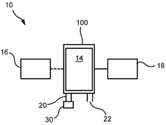
Figure 00000029_0000 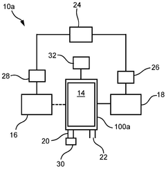
Figure 00000029_0001
Abstract
Description
[0001] Production of ammonium species
[0002] This specification claims priority to US patent application 63 / 523189 and its contents are incorporated herein by reference.
[0003] Technical field
[0004] The present invention relates to the production of ammonium-based species such as ammonium carbamate.
[0005] Background
[0006] Increased fertilizer demand has implications since practically all synthetic fertilizers are derived from fossil fuels. Whilst there has been an increase in fertilizer use as a result of increasing food demand and the goal to improve agricultural yields, there has also been a change in the type of nitrogenous fertilizer, where urea now accounts for greater than half of global nitrogenous fertiliser use. This is reflected by the fact that urea use has increased 100-fold in the past four decades.
[0007] Fertilizer production is an important contributor of Greenhouse Gas (GHG) emissions to the carbon footprint of agricultural products. The share of the global GHG emissions directly related to the production, distribution and use of fertilizers is estimated at between 2 and 3%.
[0008] Ammonia (NH3) is the primary input for the majority of nitrogen fertilizer production and all nitrogen products. The emissions from natural gas consumption are the main inputs to ammonia’s carbon footprint. However, the CO2 from synthesis gas is used in urea production and included as emissions “credit”. The production of urea is environmentally advantageous owing to the fact that it directly uses CO2 as its chemical feedstock with the stable end product and relatively high conversion. On average, it uses 0.735 to 0.75 tonnes of CO2 per tonne of urea produced.
[0009] Critical to urea production is the generation of NH3. Approximately 500 million tonnes of ammonia are produced per year via the Haber-Bosch process, accounting for 3-5% of total natural gas consumption worldwide and 2% of global energy usage.
[0010] The Haber-Bosch process requires a large fossil fuel energy input, high temperatures (400- 600 °C) and pressures (200-400 atm) as well as a significant capital investment. These intense conditions are the main disadvantages of the Haber-Bosch process, as they prevent the possibility of lowering capital costs, decentralization, and small-scale ammonia production at the level of local communities. The synthesis of ammonia at elevated pressures and temperatures via the Basaroff reaction using ammonium carbamate as an intermediate is a very energy intensive process.
[0011] It may be beneficial to find alternative processes to form ammonia and related products to help lower a carbon footprint of its production and to allow more localised manufacture.
[0012] Summary
[0013] An embodiment provides a method of forming an ammonium species, comprising: providing a reactor having a solvent in which the ammonium species is insoluble in, the solvent including protons; contacting the solvent with a nitrogen plasma such that the nitrogen plasma reacts with the protons to form ammonia that is then converted to form the ammonium species; and collecting the ammonium species that is insoluble in the solvent.
[0014] The nitrogen plasma may be a non-thermal plasma. A temperature of the solvent during formation of the ammonium species may be maintained at a temperature below a threshold value. The threshold value may be 50 °C. A concentration of the protons may range from 0.5 to 20 %(v / v). The step of contacting the solvent with the nitrogen plasma may include providing a stream of nitrogen gas and feeding the stream of nitrogen gas into a plasma generator to generate the nitrogen plasma. The plasma generator may include an anode in contact with the solvent and a cathode formed from a hollow tube. The nitrogen plasma may be generated by applying a current through the cathode as the stream of nitrogen gas is passed through the hollow tube into the reactor. An opening of the hollow tube may be positioned in a gaseous region of the reactor that is positioned above the solvent.
[0015] Collecting the ammonium species may include filtering the collected ammonium species in the solvent in which the ammonium species is insoluble in. A filtrate formed from filtering the collected ammonium species may be returned to the reactor. The solvent may include an organic solvent. The organic solvent may include methanol, ethanol, n-propanol, i-propanol, 1 ,2 propanediol, n-butanol, t-butanol, i-butanol, 2- butanol, n-amyl alcohol, i-amyl alcohol, methyl acetate, ethyl acetate, isopropyl acetate, acetone, toluene, chlorobenzene, diethyl ether, dimethyl ether, methyl ethyl ketone, and / or any miscible mixtures thereof.
[0016] The reactor may be a closed reactor. A source of the protons may include a mineral acid. The mineral acid may be nitric acid. Nitric acid may be formed by injecting an air plasma into water. The method may further comprise passing carbon dioxide through the solvent such that the ammonia reacts with the carbon dioxide to form ammonium carbamate as the ammonium species. The carbon dioxide may be passed through the solvent after the formation of ammonia. The carbon dioxide may be passed through the solvent at the same time as contacting the solvent with the nitrogen plasma.
[0017] The mineral acid may be sulphuric acid and the ammonium species may be ammonium sulphate. The mineral acid may be phosphoric acid and the ammonium species may include ammonium phosphate and / or diammonium phosphate.
[0018] The method may further comprise condensing any evaporated solvent entrained in gas that has vented from the reactor to form a condensate and returning the condensate to the reactor. An energy source used to generate the nitrogen plasma may be a renewable energy source. The nitrogen plasma may be generated at atmospheric pressure. The method may further comprise purging the reactor with nitrogen gas before generating the nitrogen plasma.
[0019] An embodiment provides a method of forming an ammonium species, comprising: providing a reactor having a solvent in which ammonium species is insoluble in, the solvent including a mineral acid; injecting into or contacting the solvent with a nitrogen plasma such that the nitrogen plasms reacts with protons to form the ammonium species; and collecting the ammonium species.
[0020] An embodiment provides a method of forming ammonium carbamate, comprising: providing a reactor having a solvent in which ammonium carbamate is insoluble in, the solvent including nitric acid; injecting into the solvent a nitrogen plasma and carbon dioxide to form ammonium carbamate; and collecting the ammonium carbamate. The carbon dioxide may be bubbled through the solvent after the nitrogen plasma is injecting into the solvent.
[0021] An embodiment provides a method of forming an ammonium phosphate species, comprising: providing a reactor having a solvent in which ammonium phosphate species is insoluble in, the solvent including phosphoric acid; injecting into or contacting the solvent with a nitrogen plasma such that the nitrogen plasma reacts with protons to form the ammonium phosphate species; and collecting the ammonium phosphate species.
[0022] An embodiment provides a method of forming ammonium sulphate, comprising: providing a reactor having a solvent in which ammonium sulphate is insoluble in, the solvent including sulphuric acid; injecting into or contacting the solvent with a nitrogen plasma such that the nitrogen plasms reacts with protons to form ammonium sulphate; and collecting the ammonium sulphate.
[0023] An embodiment provides an ammonium species formed using the method as set forth above.
[0024] An embodiment provides a method of forming urea, comprising: providing a reactor having a solvent that including protons; contacting the solvent with a nitrogen plasma such that the nitrogen plasms r reacts with the protons to form ammonia; bubbling carbon dioxide through the solvent to covert the ammonia to ammonium carbamate; and converting the ammonium carbamate to urea.
[0025] An embodiment provides a system for forming an ammonium species, comprising: a reactor having an interior volume for accommodating a solvent; a nitrogen plasma generator operably connected to the reactor for injecting a nitrogen plasma into the interior volume; and a source of nitrogen operably connected to the nitrogen plasma generator. An embodiment provides a system for forming an ammonium species, comprising: a reactor having an interior volume for accommodating a solvent, the reactor configured to accept a predefined volume of solvent to form a gaseous region positioned above an upper surface of the solvent, wherein the upper surface of the solvent falls within a solvent height range; a nitrogen plasma generator operably connected to the reactor for injecting a nitrogen plasma into the interior volume; and a nitrogen source operably connected to the nitrogen plasma generator.
[0026] The system may further comprise a proton source for injecting protons into the solvent that is used in the reactor. The proton source may include a supply of mineral acid. The proton source may include an air plasma generator configured to inject an air plasma into water to generate the protons. The nitrogen source may include a nitrogen generator that generates nitrogen from air. The nitrogen plasma generator may include: an anode positioned below the solvent height range so as to be immersed, in use, in the solvent; a cathode formed from a hollow tube that opens out into the gaseous region, wherein the hollow tube is in fluid communication with the nitrogen source such that the nitrogen source can pass through the hollow tube into the interior volume; and a current generator for generating a current between the cathode and anode.
[0027] The system may further comprise a carbon dioxide source operably connected to the reactor such that in use carbon dioxide gas can be passed through the solvent in the reactor. The system may further comprise a gas outlet and a condenser in fluid communication with the gas outlet. The condenser may be configured to condense any evaporated solvent entrained in gas passing through the gas outlet and return the condensed solvent back to the interior volume.
[0028] The system may further comprise a filter operably connected to a product outlet of the reactor for filtering the ammonium species formed in the reactor from the solvent. The system may further comprise a cooling system that is configured to maintain a temperature of the solvent below a threshold value.
[0029] The threshold value may be 50 °C. An energy source used to power the nitrogen plasma may be a renewable energy source. The nitrogen plasma generator may be configured to generate the nitrogen plasma at atmospheric pressure. The reactor may be a closed reactor.
[0030] An embodiment provides use of the system as set forth above to form an ammonium species.
[0031] Brief Description of the Drawings
[0032] Embodiments will now be described, by way of example only, with reference to the accompanying non-limiting drawings, in which:
[0033] Figure 1 is a schematic representation of an embodiment of a system used to form an ammonium species.
[0034] Figure 2 is a schematic representation of another embodiment of a system used to form an ammonium species.
[0035] Figure 3 is a schematic representation of an embodiment of a system used to produce an ammonium species.
[0036] Figure 4 is a schematic representation another embodiment of a system used to produce an ammonium species.
[0037] Figure 5 is a schematic representation another embodiment of a system used to produce an ammonium species.
[0038] Detailed Description
[0039] Embodiments of the disclosure relate to methods and systems used to form ammonium-based species.
[0040] Figure 1 shows an embodiment of a system 10 used to form an ammonium species. The system 10 includes a reactor 100 that has an interior volume 14. The interior volume 14 accommodates a solvent. In an embodiment, the reactor 100 is configured to accept a predefined volume of solvent. A nitrogen plasma generator 18 is connected to the reactor 100 and is configured to inject a nitrogen plasma into the interior volume 14. The nitrogen plasma generator 18 includes an anode that is positioned to be placed in the solvent in use, a cathode generally associated with delivery of nitrogen gas, and a current generator for generating a current between the anode and cathode. The current generator is not depicted in the figures but is associated with the nitrogen plasma generator 18. In an embodiment, the nitrogen plasma generated by the nitrogen plasma generator 18 is injected into a solvent that is accommodated in the interior volume 14 during use of the system 10 to form an ammonium species. The nitrogen plasma generator 18 is connected to a nitrogen source (not shown in Figure 1 ). The nitrogen source is described in more detail with reference to Figure 2.
[0041] The system 10 also includes a proton source 16 that is configured to inject or provide protons to the solvent used in the reactor 100. In an embodiment, the proton source is operably connected to the reactor 100. For example, the proton source 16 may inject or supply protons to the solvent already accommodated in the interior volume 14. In such an example, the reactor 100 would include an inlet port for passing at least some of the proton source into the interior volume 14. This arrangement may allow for a continual flow of protons to be supplied to the solvent in the interior volume 14. In another example, at least some protons from the proton source may be mixed with the solvent prior to accommodation / injection in the interior volume 14. Mixing the protons with the solvent prior to accommodation / injection in the interior volume 14 may help to reduce or eliminate the requirement for an internal wall of the reactor 100 that defines the interior volume 14 to be of a higher-grade acid resistance.
[0042] In use of the system 10, the nitrogen plasma formed by the nitrogen plasma generator 18 reacts with the protons, or at least catalyses the transformation of the protons, in the solvent to form ammonia, represented generally by Equation 1 .
[0043] Equation 1 : N2+ 6H++ 6e_-> 2NH3
[0044] Although Equation 1 shows the general equation to form ammonia, there may be side reactions that produce by-products in addition to ammonia. The ammonia formed is generally solubilised in the solvent, although it should be appreciated that a concentration of the ammonia in the solvent is dependent upon a temperature of the and a polarity of the solvent, and that the ammonia may be partitioned between the solvent and a headspace above the solvent. Any additional reactants (R) added to or already provided in the solvent can react with the ammonia to form the ammonium species, as shown generally in Equation 2. If the reactant (R) is provided in the solvent prior to generation of the nitrogen plasma, the reactant (R) may react with the ammonia as soon as the ammonia is formed. Alternatively, a reactant (Ft) may be added to the solvent after the formation of ammonia.
[0045] Equation 2: nR + yNH3-» (NH4)yRn
[0046] Generating the ammonium species using a plasma may offer a highly efficient and cost-effective alternative to traditional methods of ammonium production and related products such as urea. Without being bound by theory, the plasma serves as a highly active catalyst, promoting the formation of ammonia and related products formed by reaction of the ammonia with a reactant at much faster rates than traditional methods. Additionally, the use of a nitrogen gas source as the feedstock may eliminate the need for expensive and hard-to-obtain reactants. If a renewable energy source is used to power the nitrogen plasma generator, the system 10 and its use to form ammonium species may also have a low environmental impact as it requires less energy and raw materials and generates less waste than traditional methods. The use of a nitrogen plasma may also help to reduce capital and operational expenses as the reaction conditions may not require high pressures and temperatures commonly found in the production of ammonia and / or ammonium species.
[0047] The solvent used in the reactor 100 is selected such that the reactants (e.g. protons) are soluble in the solvent, but the ammonium species is insoluble in the solvent (i.e. precipitates out). In an embodiment, the solvent used in the reactor 100 is or includes an organic solvent. In an embodiment, the organic solvent includes methanol, ethanol, n-propanol, i-propanol, 1 ,2 propanediol, n-butanol, t-butanol, i-butanol, 2-butanol, n- amyl alcohol, i-amyl alcohol, methyl acetate, ethyl acetate, isopropyl acetate, acetone, toluene, chlorobenzene, diethyl ether, dimethyl ether, methyl ethyl ketone, and / or any miscible mixtures thereof. Using a solvent that the ammonium species is insoluble in may help to facilitate separation of the ammonium species from the solvent and any remaining reactants. For example, precipitation of the ammonium species during its formation according to Equation 2 helps to shift the equilibrium of both Equation 1 and Equation 2 to the right thereby helping to improve yields.
[0048] To assist with precipitation of the ammonium species, the solvent may have a maximum water content threshold. The solvent may be anhydrous. The solvent may be substantially free from water e.g. >1 %(v / v) water. The solvent may have up to 5 %(v / v) water. The solvent may have up to 10 %(v / v) water. Being able to accommodate water in the solvent may allow the use of ‘lab grade’ or ‘second grade’ solvents that are not purified to higher levels, which may help to reduce the costs of forming the ammonium species.
[0049] The system 10 has an outlet 20 that is in fluid communication with a filter 30. After the formation of the ammonium species, the reaction mixture (i.e. solvent, unreacted reactants, ammonium species, and so on) is passed through outlet 20 and then through filter 30. The ammonium species is collected in the filter 30 and the filtrate can be collected. In an embodiment, the filtrate is returned to the interior volume 14 to help reduce consumption of solvent and reactants. Any ammonium species collected in the filter 30 can be further washed such as with fresh solvent. The outlet 20 may have an associated pump for pumping the reactant mixture out of the interior volume 14. In an embodiment, the reaction mixture is removed from the interior volume through gravity.
[0050] It should be noted that the embodiments shown in Figures 1 and 2 are schematic in nature and are not depicted to define a specific orientation. Accordingly, features such as the outlet 20 and filter 30 which are shown as being on a ‘bottom’ side of the reactor, may be positioned at any location on the reactor 100.
[0051] A temperature of the solvent in the interior volume 14 may be maintained at a temperature below a threshold temperature. The threshold temperature may be a boiling point of the solvent. The threshold temperature may be 100 °C. The threshold temperature may be 95 °C. The threshold temperature may be 90 °C. The threshold temperature may be 85 °C. The threshold temperature may be 80 °C. The threshold temperature may be 75 °C. The threshold temperature may be 70 °C. The threshold temperature may be 65 °C. The threshold temperature may be 60 °C. The threshold temperature may be 55 °C. The threshold temperature may be 50 °C. The threshold temperature may be 45 °C. The threshold temperature may be 40 °C.
[0052] A temperature of the solvent and / or the reactor 100 may be controlled using a temperature control system 130 as is described in more detail with reference to Figure 3 and Figure 4.
[0053] The proton source may be a proton donor or acidic electrolyte. The proton source may be an organic acid. The organic acid may include formic acid, acetic acid, carbonic acid, dicarbonic acid, oxalic acid and / or mixtures thereof. The proton source may be a mineral or inorganic acid. The mineral or inorganic acid may include hydrochloric acid, sulphuric acid, sulphurous acid, phosphoric acid, nitric acid and / or nitrous acid. The type of ammonium species will depend, in part, on the proton source used. For example, sulphuric acid generally results in the formation of ammonium sulphate, and phosphoric acid generally results in the formation of ammonium phosphate and / or diammonium phosphate.
[0054] The proton source may be generated by electrochemical means such as electrolysis, coupled electron transfer and photocatalysis. In an embodiment, the proton source is provided by injecting an air plasma into water. Use of an air plasma to generate the proton source is described in greater detail with reference to Figure 2.
[0055] A concentration of the protons in the solvent is selected to shift the equilibrium of Equation 1 to the right to promote the formation of ammonia. However, the concentration of the protons needs to be balanced with any associated water than may accompany the proton. For example, if the proton source is nitric acid, the solvent may have up to about 10 %(v / v) of concentrated nitric acid (68% HNOs). A concentration of the protons in the solvent may range from 0.5 to 20 %(v / v). A concentration of the protons in the solvent may range from 0.5 to 15 %(v / v). A concentration of the protons in the solvent may range from 0.5 to 10 %(v / v). A concentration of the protons in the solvent may range from 0.5 to 5 %(v / v). A concentration of the protons in the solvent may be equal to or less than 5 %(v / v). A concentration of the protons in the solvent may be 5 %(v / v). A concentration of the protons in the solvent may be 4 %(v / v). A concentration of the protons in the solvent may be 3 %(v / v). A concentration of the protons in the solvent may be 1 %(v / v).
[0056] In an embodiment, the reactor 100 in system 10 is a closed reactor. When a closed reactor is used, a gas outlet 22 may be provided. The gas outlet 22 can also be termed a vent. The gas outlet 22 allows gases introduced into the interior volume 14 of the reactor 100 to escape. For example, a purging gas may be used to purge the interior volume 14 prior to the formation of the ammonium species, with the purging gas venting through the gas outlet 22 thereby maintaining the reactor 100 at atmospheric pressure. The gas outlet 22 may be provided with a valve to close the gas outlet 22, for example if the formation of the ammonium species is performed under pressure. The gas outlet 22 may be provided with a pressure relief valve that ensures a pressure of gas in the interior volume 14 can only reach a maximum pressure. The reactor 100 may be a pressure reactor. For example, the nitrogen plasma may be generated above atmospheric pressures such as up to 10 atm. The nitrogen plasma may be generated at a pressure up to 9 atm. The nitrogen plasma may be generated at a pressure up to 8 atm. The nitrogen plasma may be generated at a pressure up to 7 atm. The nitrogen plasma may be generated at a pressure up to 6 atm. The nitrogen plasma may be generated at a pressure up to 5 atm. The nitrogen plasma may be generated at a pressure up to 4 atm. The nitrogen plasma may be generated at a pressure up to 3 atm. The nitrogen plasma may be generated at a pressure up to 2 atm. Without being bound by theory, it is believed that increasing a pressure inside the reactor 100 may help to increase a solubility of the plasma in the solvent 124.
[0057] Another embodiment of a system 10a used to form an ammonium species will now be described with reference to Figure 2. Like features in system 10 are referenced using the same numerical references in system 10a. System 10a includes reactor 100a. In System 10a, an air supply 24 is fluidly connected to a nitrogen generator 26. The air supply 24 may be compressed air, such as that in a cannister or cylinder, or may include a compressor. The nitrogen generator 26 is fluidly connected to the nitrogen plasma generator 18. Air supplied to the nitrogen generator 26 is filtered / purified to produce a stream of nitrogen (e.g. nitrogen gas) to the nitrogen plasma generator 18. Use of nitrogen generator 26 in combination with the air supply 24 may help to eliminate the need to nitrogen cylinders and the like to supply nitrogen to the nitrogen plasma generator 18. The nitrogen generator 26 is not required in all embodiments and may instead be replaced with a dedicated nitrogen source such as cannisters or cylinders of nitrogen gas. Therefore, the nitrogen source used to provide a stream of nitrogen to the nitrogen plasma generator 18 can include plumbed nitrogen, nitrogen boiloff from a liquid nitrogen source, compressed nitrogen gas such as that stored in a cylinder, and / or from a nitrogen generator.
[0058] In an embodiment, system 10a has an air plasma generator 28 fluidly connected to the air supply 24. The air plasma generator 28 is configured to inject an air plasma into water to generate the protons. This proton solution can then be added or combined with the solvent that is used in the reactor 100a. In an embodiment, the protons formed by the air plasma generator 28 are in the form of nitric acid. Using an air plasma to generate the protons removes the need to supply and store mineral acids, which may improve the safety of the system 10a and its associated used. Use of the air supply 24 in combination with the air plasma generator 28 for generating the protons and the nitrogen generator 26 for supplying the nitrogen plasma generator 18 can help to reduce an operational cost of the system 10a and simplify generation of ammonium species, especially for remote locations such as farms where the system 10a may be used to generate e.g. fertilisers on site.
[0059] The system 10a also includes a carbon dioxide source 32. The carbon dioxide source 32 is operably connected to the reactor 100 and is configured to pass carbon dioxide through the solvent in the interior volume 14. Carbon dioxide can react with the generated ammonia to form ammonium carbamate according to Equation 3. The carbon dioxide may be passed through the solvent in the interior volume 14 during the formation of ammonia with the nitrogen plasma or may be passed through the solvent after the formation of ammonia.
[0060] Equation 3: 2NH3+ CO2[NH2CO2][NH4]
[0061] In an embodiment, carbon dioxide gas from the carbon dioxide source 32 is combined with the stream of nitrogen. Such an arrangement may allow for fewer input ports into the reactor 100a. A nitrogen-carbon dioxide gas mix used to form a plasma may form a combination of a nitrogen plasma and carbon dioxide plasma. The carbon dioxide source 32 may include flue gas. The carbon dioxide source 32 may include a filter to remove gaseous products other than carbon dioxide.
[0062] The carbon dioxide source 32 is not required in all embodiments depending on the desired ammonium species. Therefore, system 10a does not always include carbon dioxide source 32.
[0063] The ammonium carbamate formed in system 10a may be collected by filtration. Filtration can include washing steps to remove residual ammonium and other reactants. Alternatively, the ammonium carbamate may be isolated in the reactor, such as by removal of solvent. The collected ammonium carbamate can then be converted to urea by dehydration according to Equation 4. Because formation of urea generates water, it may be advantageous to prevent the formation of urea during the formation of ammonium carbamate otherwise the ammonium carbamate and / or urea may become solubilised in the solvent.
[0064] Equation 4: [NH2CO2KNH4] (NH2)2CO + H2O Therefore, an embodiment provides a method of forming urea, comprising: providing reactor 100 / 100a having a solvent that includes protons formed from injecting an air plasma from air plasma generator 28 into water; contacting the solvent with a nitrogen plasma from nitrogen plasma generator 18 that reacts with the protons to form ammonia; bubbling carbon dioxide through the solvent from carbon dioxide source 32 to covert the ammonia to ammonium carbamate; and converting the ammonium carbamate to urea, such as through dehydration.
[0065] The nitrogen plasma is formed by passing nitrogen, typically in gaseous form, through the nitrogen plasma generator 18. The interior volume 14 may be purged with nitrogen gas prior to forming the nitrogen plasma from nitrogen plasma generator 18. Purging the interior volume 14 may help to reduce unwanted side reactions, such as those formed by interaction of plasma with air. The stream of nitrogen gas may be continually passed through the interior volume 14 and vented through gas outlet 22. This may help to drive of gaseous by-products and help to maintain or reduce any water or humidity that may occur during the formation of the ammonium species.
[0066] In an embodiment, the nitrogen plasma is a non-thermal plasma. Therefore, the nitrogen plasma generator 18 may be a non-thermal plasma generator. The non- thermal plasma can be generated via a number of different methods, such as plasma jet, corona discharge, dielectric barrier discharge (DBD), gliding arc, or micro hollow cathode discharge (MHCD) and electrode with a gas gap between the electrode and the solvent. The nitrogen plasma may have different intensities and properties depending on its mode of formation and required reaction conditions.
[0067] The nitrogen plasma may be formed at atmospheric pressures. The nitrogen plasma may be formed at pressures above atmospheric pressures. If required, the nitrogen source used by the nitrogen plasma generator 18 may include a mixture of gases. For example, nitrogen may be entrained in a carrier gas such as an inert gas. Other gas mixture(s) may be utilised depending on the type of ammonium species formed and / or formation of a specific nitrogen compound. Therefore, the nitrogen source can include nitrogen gas mixed with one or more of air, flue gas, dehumidified flue gas, carbon dioxide, nitric oxide, nitrous oxide, dinitrogen oxide, sulphur dioxide, oxygen, argon and helium.
[0068] Embodiments of the reactor 100 and reactor 100a will now be described in more detail with reference to Figure 3 and Figure 4.
[0069] An embodiment of a reactor 100a is shown in Figure 3. The reactor 100a includes a vessel 108 that defines the interior volume 14. The interior volume 14 accommodates a predefined volume of solvent 124. In Figure 3, a height of the solvent 124 of the predefined volume falls within an upper and lower height range as represented by upper solvent height limit line 125a and lower solvent height limit line 125b. The upper solvent height limit line 125a and lower solvent height limit line 125b define a solvent height range. An upper surface of the solvent 124 is represented by solvent surface 126 and falls within the upper solvent height limit line 125a and lower solvent height limit line 125b. The predefined volume of solvent 124 is less than a total volume of the interior volume 14 such that a headspace or gaseous region 122 is formed above the solvent surface in use of the reactor 100. It should be appreciated that a level of the solvent surface may fluctuate during use of the reactor 100 due to e.g. stirring, mixing, and bubbling of gases.
[0070] Associated with the reactor 100a is the nitrogen plasma generator 18. In an embodiment, the nitrogen plasma generator 18 has a conduit in the form of hollow tube 116 that passes through the vessel 108 such that an opening 120 of the hollow tube 116 opens out into the gaseous region 122. The opening 120 is positioned above the upper solvent height limit line 125a such that the opening 120 is always positioned above the solvent surface 126. In an embodiment, the opening 120 is positioned at least 1 mm above the solvent surface 126. In an embodiment, the hollow tube 116 is adjustable in an axial direction to adjust a distance from the opening 120 to the solvent surface 126.
[0071] Nitrogen gas can pass through the hollow tube 116 into the gaseous region 122. If carbon dioxide gas, or any other gas, is combined with or entrained in the nitrogen gas, they can also be passed through the hollow tube 116 into the gaseous region 122 with the nitrogen gas. The hollow tube 116 forms a cathode. The nitrogen plasma generator 18 also has an anode 118 that extends through the vessel 108 such that a terminal region 119 of the anode contacts the solvent 124. In the embodiment shown in Figure 3, the terminal region 119 is positioned below the lower solvent height limit line 125b so as to be immersed in the solvent 124. In use of the nitrogen plasma generator 18, a current is passed through the hollow tube 116 (i.e. cathode) as the stream of nitrogen is passed through the hollow tube 116, thereby forming a nitrogen plasma that can be directed or injected into the solvent 124. The relative positions of the opening 120 and anode 118 in Figure 3 and Figure 4 are exemplary only and do not place any positional or structural relationship with respect to other features of the reactor 100 and reactor 100a.
[0072] In an embodiment, the hollow tube 116 is replaced with a solid cathode i.e. one that is not hollow (not shown). The positioning of the solid cathode is the same as for the hollow tube 116. When a solid cathode is used, a separate inlet for nitrogen gas is used to supply a stream of nitrogen to form the nitrogen plasma.
[0073] The geometry of the hollow tube 116 and any other cathode used in nitrogen plasma generator is not limited to that depicted in the Figures which are exemplary only, and the cathode used in the nitrogen plasma generator may adopt different geometries depending on properties such as reactor 100 design, scale of ammonium-species formation, flow rate of nitrogen source, and so on.
[0074] An input power to the nitrogen plasma generator 18 may be about 100W. An input power to the nitrogen plasma generator 18 may be about 200W. An input power to the nitrogen plasma generator 18 may be about 300W. An input power to the nitrogen plasma generator 18 may be about 400W. An input power to the nitrogen plasma generator 18 may be about 500W. An input power to the nitrogen plasma generator 18 may be about 600W. An input power to the nitrogen plasma generator 18 may be about 700W. An input power to the nitrogen plasma generator 18 may be about 800W. An input power to the nitrogen plasma generator 18 may be about 900W. An input power to the nitrogen plasma generator 18 may be about 1 ,000W. An input power to the nitrogen plasma generator 18 may be greater than 1 ,000W.
[0075] An output discharge of the nitrogen plasma generator 18 may have a frequency of about 16kHz. An output discharge of the nitrogen plasma generator 18 may be at least 5kV. An output discharge of the nitrogen plasma generator 18 may be at least 10kV. An output discharge of the nitrogen plasma generator 18 may be at least 15kV. An output discharge of the nitrogen plasma generator 18 may be at most 20kV. An output discharge of the nitrogen plasma generator 18 may be at most 15kV. An output discharge of the nitrogen plasma generator 18 may be at most 10kV. An output discharge of the nitrogen plasma generator 18 may be range from 5kV to 20kV.
[0076] A flow rate of nitrogen gas through the hollow tube 116 may be at least 1 L / min. A flow rate of nitrogen gas through the hollow tube 116 may be at least 5L / min. A flow rate of nitrogen gas through the hollow tube 116 may be at least 10L / min. A flow rate of nitrogen gas through the hollow tube 116 may be at least 15L / min. A flow rate of nitrogen gas through the hollow tube 116 may be at least 20L / min. A flow rate of nitrogen gas through the hollow tube 116 may be at least 25L / min. A flow rate of nitrogen gas through the hollow tube 116 may be at least 30L / min. A flow rate of nitrogen gas through the hollow tube 116 may be up to 50L / min. A flow rate of nitrogen gas through the hollow tube 116 may be up to 40L / min. A flow rate of nitrogen gas through the hollow tube 116 may be up to 30L / min. A flow rate of nitrogen gas through the hollow tube 116 may be up to 20L / min. A flow rate of nitrogen gas through the hollow tube 116 may be up to 10L / min. A flow rate of nitrogen gas through the hollow tube 116 may range from 5L / min to 30L / min.
[0077] The reactor 100a also has a condenser 114 fitted to the gas outlet 22. During use of the reactor 100a, the solvent 124 may be heated such that a solvent vapour is formed by evaporation. The condenser 114 helps to return condensed vapour back to the solvent 124, thereby helping to maintain a solvent height within the upper and lower solvent height limit line 125a and 125b. The solvent vapour may be entrained in a gas that passes through the gaseous region 122 such as nitrogen gas from the nitrogen plasma generator 18.
[0078] When the carbon dioxide source 32 is utilised, a conduit 112 in fluid communication with the carbon dioxide source 32 passes through the vessel 108 and opens out at opening 128 into the solvent 124. In an embodiment, the opening 128 is positioned below the lower solvent height limit line 125b such that carbon dioxide exiting the opening 128 bubbles through the solvent 124. Having the opening 128 be positioned below the lower solvent height limit line 125b can help to ensure that carbon dioxide is always bubbled through the solvent 124 helping to saturate the solvent 124 with carbon dioxide as carbon dioxide. In an embodiment, the opening 128 is positioned in the gaseous region 122.
[0079] A flow rate of carbon dioxide through the conduit 112 may be at least 1 L / min. A flow rate of carbon dioxide through the conduit 112 may be at least 5L / min. A flow rate of carbon dioxide through the conduit 112 may be at least 10L / min. A flow rate of carbon dioxide through the conduit 112 may be at least 15L / min. A flow rate of carbon dioxide through the conduit 112 may be at least 20L / min. A flow rate of carbon dioxide through the conduit 112 may be at least 25L / min. A flow rate of carbon dioxide through the conduit 112 may be at least 30L / min. A flow rate of carbon dioxide through the conduit 112 may be up to 50L / min. A flow rate of carbon dioxide through the conduit 112 may be up to 40L / min. A flow rate of carbon dioxide through the conduit 112 may be up to 30L / min. A flow rate of carbon dioxide through the conduit 112 may be up to 20L / min. A flow rate of carbon dioxide through the conduit 112 may be up to 10Umin. A flow rate of carbon dioxide through the conduit 112 may range from 5L / min to 30L / min.
[0080] Reactor 100a is configured to form ammonium carbamate in accordance with Equation 3. The spatial relationship of the opening 120 on hollow tube 116 (i.e. the cathode) being above the upper solvent height limit line 125a and the opening 128 of conduit 112 being below the lower solvent height limit line 125b helps to promote high conversion of the ammonia to ammonium carbamate.
[0081] In an embodiment, reactor 100a includes two sub-reactor units (not shown). One subreactor unit is fitted with the nitrogen plasma generator 18 and is configured to form ammonia, and the other sub-reactor unit is fitted with the carbon dioxide source 32 and is configured to convert ammonia to ammonium carbamate. The use of the two subreactor units can help to provide more continuous-flow reaction conditions and / or speed up the formation of ammonium carbamate.
[0082] The reactor 100a also has a cooling system in the form of temperature control system 130. The temperature control system 130 helps to maintain a temperature of at least the solvent 124 to be within a predefined temperature condition such as below a threshold value. In an embodiment, the temperature control system is configured to maintain a temperature of the solvent 124 below a threshold temperature. The temperature control system 130 may be embodied in many forms, but generally will include a heat exchange fluid. It should be appreciated that the need for the temperature control system 130 is dependent upon the reaction conditions in the reactor 100 and reactor 100a and accordingly that the temperature control system 130 is not required in all embodiments. An example embodiment of forming ammonium carbamate using reactor 100a will now be described. The solvent 124 is fed into the interior volume 14, for example through an access port or valve 21 fitted to outlet 20. In an embodiment, the reactor 100a is provided with an inlet port separate to outlet 20. Protons are typically added to the solvent 124 to form a proton-charged solvent. For example, a mineral acid may be added to the solvent 124. Alternatively, the protons may be generated using air plasma generator 28 prior to feeding the solvent into the reactor 100a but may also be added to the solvent after the solvent has been fed into the reactor 100a. The reactor 100a is then closed and nitrogen gas, or a gas mixture including nitrogen, is purged through the interior volume 14 to provide a nitrogen or nitrogen rich environment. After purging, a current is applied to the cathode (i.e. hollow tube 116) where a nitrogen plasma is generated and injected into the solvent 124. During this time the temperature control system 130 may be activated to maintain the reaction conditions within a predefined temperature condition. After sufficient time has passed to form ammonia, the current and flow of nitrogen gas through the hollow tube 116 is stopped, and carbon dioxide is then bubbled through the solvent via conduit 112 to convert ammonia to ammonium carbamate. As the ammonium carbamate is formed, it precipitates out of the solvent 124 (due to the solvent selection as outlined above). The suspension of ammonium carbamate in the solvent 124 is then passed through outlet 20 and the ammonium carbamate is collected and washed in filter 30.
[0083] Another embodiment of a reactor 100 will now be described with reference to Figure 4. Reactor 100 is similar to reactor 100a and like references are used to describe like features. The main difference between reactor 100a and 100 is that the carbon dioxide source 32 is omitted from reactor 100. Therefore, reactor 100 is not configured to form ammonium carbamate, but instead is configured to form other ammonium species. For example, sulphuric acid can be added to the solvent 124 allowing the formation of ammonium sulphate upon generation of ammonia. Apart from the carbon dioxide source 32, reactor 100 and reactor 100a are operated in a similar manner.
[0084] Another embodiment of a reactor 100b is shown with reference to system 10b. System 10b is similar to system 10a and like references are used to describe like features. The specific representation of features of system 10b in Figure 5 is exemplary and used only to help in describing the features of the embodiments. For example, the specific location of the hollow tube 116 relative the anode 118 and outlet 20 is an example only. The main difference between reactor 100a and reactor 100b is that orientation and form of the nitrogen plasma generator 18. In reactor 100b, the hollow tube 116 is arranged to be positioned in the solvent 124. The hollow tube 116 is also provided with one or more openings 120a. The one or more openings 120a are provided in the side of the hollow tube 116, specifically an upper side of the hollow tube 116. The anode 118 is also provided at or toward a bottom of the vessel 108 such that the terminal region 119 is positioned below the hollow tube 116. As nitrogen is passed through the hollow tube 116, bubbles of nitrogen gas are formed in the solvent 124 that are then converted into a plasma in the form of plasma plume 132 by application of a potential between the anode 118 and a cathode of the nitrogen plasma generator 18 which may include the hollow tube 116 or a component in the hollow tube 116. In this way, the plasma plume 132 is contacted with the solvent 124 as a bubble in the solvent 124.
[0085] The ’’bubble” arrangement of the nitrogen plasma generator 18 in reactor 100b is only exemplary and may be embodied in other forms. For example, a nitrogen inlet can introduce nitrogen gas into the solvent 124 towards a bottom of the vessel 108, and the nitrogen plasma generator 18 can have anode 118 positioned at or in one sidewall of the vessel 108 with the associated cathode an opposite sidewall. Alternatively, a bottom portion of the vessel 108 may include a gas-permeable membrane that allows nitrogen gas to pass therethrough into the solvent 124. The gas-permeable membrane can include a cathode of the nitrogen plasma generator 18 with the anode 118 positioned at or defining a side of the gas-permeable membrane.
[0086] The system 10b may also include an agitator (not shown). The agitator helps to agitate the solvent 124 to control a size of the bubbles formed by the plasma plume 132. The agitator may include a stirring mechanism and / or sonication.
[0087] In the claims that follow and in the preceding description of the invention, except where the context requires otherwise due to express language or necessary implication, the word “comprise” or variations such as “comprises” or “comprising” is used in an inclusive sense, i.e. to specify the presence of the stated features but not to preclude the presence or addition of further features in various embodiments of the invention.
[0088] It is to be understood that, if any prior art publication is referred to herein, such reference does not constitute an admission that the publication forms a part of the common general knowledge in the art, in Australia or any other country. Modifications and variations as would be apparent to a skilled addressee are deemed to be within the scope of the present invention.
[0089] Examples
[0090] Embodiments will now be described with reference to the following non-limiting examples.
[0091] Example 1 - Ammonium carbamate formation
[0092] A solvent solution (100ml) formed from ethanol, water (up to 10%v / v) and nitric acid, and having a pH < 3.5 was added to a reactor having a nitrogen plasma generator having a hollow cathode and anode. The nitric acid may be concentrated nitric acid or formed from an air plasma discharge into water. A solvent height was such that a distance between a surface of the solvent and a tip of the hollow cathode is at least 1 mm.
[0093] The reactor was closed and purged with nitrogen gas at a flow rate of 5-30L / min for 2 minutes after which the nitrogen plasma generator was supplied with an input of 300W to produce a discharge of approximately 16kHz at 5.20kV to inject a nitrogen plasma into the solvent to form ammonia. The nitrogen plasma was injected into the solvent for up to 1 hour after which the flow of nitrogen gas and current supplied to the nitrogen plasma generator was stopped. Carbon dioxide gas was then bubbled through the solvent at a flow rate of 5-30L / min to convert the ammonia to ammonium carbamate. The flow of carbon dioxide gas was stopped once no more precipitate formed. The precipitate is predominantly ammonium carbamate but may also contain ammonium carbonate and / or ammonium bicarbonate.
[0094] The solvent was passed through a filter to collect ammonium carbamate which was then washed with fresh ethanol.
[0095] The ammonium carbamate could optionally then be converted to urea through dehydration.
[0096] A solvent solution (100ml) formed from ethanol, water (up to 10%v / v) and sulphuric acid, and having a pH < 3.5 was added to a reactor having a nitrogen plasma generator having a hollow cathode and anode. A solvent height was such that a distance between a surface of the solvent and a tip of the hollow cathode is at least 1 mm.
[0097] The reactor was closed and purged with nitrogen gas at a flow rate of 5-30L / min for 2 minutes after which the nitrogen plasma generator was supplied with an input of 300W to produce a discharge of approximately 16kHz at 5.20kV to inject a nitrogen plasma into the solvent to form ammonia which was then protonated to form ammonium sulphate which precipitated from the solvent. The nitrogen plasma was injected into the solvent for up to 1 hour. The flow of nitrogen gas was stopped once no more precipitate formed.
[0098] The solvent was then passed through a filter to collect ammonium sulphate which was then washed with fresh ethanol and dried.
[0099] Example 3 - Ammonium phosphate / ammonium diphosphate formation
[0100] A solvent solution (100ml) formed from ethanol, water (up to 10%v / v) and phosphoric acid, and having a pH < 3.5 was added to a reactor having a nitrogen plasma generator having a hollow cathode and anode. A solvent height was such that a distance between a surface of the solvent and a tip of the hollow cathode is at least 1 mm.
[0101] The reactor was closed and purged with nitrogen gas at a flow rate of 5-30L / min for 2 minutes after which the nitrogen plasma generator was supplied with an input of 300W to produce a discharge of approximately 16kHz at 5.20kV to inject a nitrogen plasma into the solvent to form ammonia which was then protonated to form ammonium phosphate and / or ammonium diphosphate which precipitated from the solvent. The nitrogen plasma was injected into the solvent for up to 1 hour. The flow of nitrogen gas was stopped once no more precipitate formed.
[0102] The solvent was then passed through a filter to collect ammonium phosphate and / or ammonium diphosphate which was then washed with fresh ethanol and dried.
[0103] Example 4 - Ammonium sulphate formation
[0104] A reaction chamber has a 5 mm borosilicate tube having a dielectric barrier and tungsten element (forming the nitrogen plasma generator) was charged with food grade nitrogen. The nitrogen flow rate is 1 -2 litres per minute
[0105] The reaction chamber was also charged with ethanol (60mL) sulphuric acid (2ml_), and a voltage of 15 Kvolts DC was applied at a rate of 0.9W for 0.75 hours (equating to 0.68 Wh).
[0106] Ammonium sulphate precipitated from the ethanol. An ammonia content was measured using Nessler's reagent (NaOH / KI / Hgl) against a standard curve at 420nm. An ammonia content of 4.6 mg was measured, which equated to an ammonium sulphate content of 15.6 mg.
Claims
Claims1 . A method of forming an ammonium species, comprising: providing a reactor having a solvent in which the ammonium species is insoluble in, the solvent including protons; contacting the solvent with a nitrogen plasma such that the nitrogen plasma reacts with the protons to form ammonia that is then converted to form the ammonium species; and collecting the ammonium species that is insoluble in the solvent.
2. A method according to claim 1 , wherein the nitrogen plasma is a non-thermal plasma.
3. A method according to claim 1 or 2, wherein a temperature of the solvent during formation of the ammonium species is maintained at a temperature below 50 °C.
4. A method according to any one of claims 1 to 3, wherein a concentration of the protons ranges from 0.5 to 20 %(v / v).
5. A method according to any one of claims 1 to 4, wherein contacting the solvent with the nitrogen plasma includes providing a stream of nitrogen gas and feeding the stream of nitrogen gas into a plasma generator to generate the nitrogen plasma.
6. A method according to claim 5, wherein the plasma generator includes an anode in contact with the solvent and a cathode formed from a hollow tube, wherein the nitrogen plasma is generated by applying a current through the cathode as the stream of nitrogen gas is passed through the hollow tube into the reactor.
7. A method according to claim 6, wherein an opening of the hollow tube is positioned in a gaseous region of the reactor that is positioned above the solvent.
8. A method according to claim 6, wherein an opening of the hollow tube is positioned in the solvent.
9. A method according to any one of claims 1 to 8, wherein collecting the ammonium species includes filtering the collected ammonium species in the solvent in which the ammonium species is insoluble in.
10. A method according to claim 9, wherein a filtrate formed from filtering the collected ammonium species is returned to the reactor.
11. A method according to any one of claims 1 to 10, wherein the solvent includes an organic solvent.
12. A method according to claim 11 , wherein the organic solvent includes methanol, ethanol, n-propanol, i-propanol, 1 ,2 propanediol, n-butanol, t-butanol, i-butanol, 2-butanol, n-amyl alcohol, i-amyl alcohol, methyl acetate, ethyl acetate, isopropyl acetate, acetone, toluene, chlorobenzene, diethyl ether, dimethyl ether, methyl ethyl ketone, and / or any miscible mixtures thereof.
13. A method according to any one of claims 1 to 12, wherein the reactor is a closed reactor.
14. A method according to any one of claims 1 to 13, wherein a source of the protons includes a mineral acid.
15. A method according to claim 14, wherein the mineral acid is nitric acid.
16. A method according to claim 15, wherein the nitric acid is formed by injecting an air plasma into water.
17. A method according to any one of claims 1 to 16, further comprising passing carbon dioxide through the solvent such that the ammonia reacts with the carbon dioxide to form ammonium carbamate as the ammonium species.
18. A method according to claim 17, wherein the carbon dioxide is passed through the solvent after formation of ammonia.
19. A method according to claim 14, wherein the mineral acid is sulphuric acid andthe ammonium species is ammonium sulphate.
20. A method according to claim 14, wherein the mineral acid is phosphoric acid and the ammonium species includes ammonium phosphate and / or diammonium phosphate.21 . A method according to any one of claims 14 to 20, wherein a concentration of the mineral acid is up to 20% (v / v).
22. A method according to any one of claims 1 to 21 , further comprising condensing any evaporated solvent entrained in gas that has vented from the reactor to form a condensate and returning the condensate to the reactor.
23. A method according to any one of claims 1 to 22, wherein an energy source used to generate the nitrogen plasma is a renewable energy source.
24. A method according to any one of claims 1 to 23, wherein the nitrogen plasma is generated at atmospheric pressure.
25. A method according to any one of claims 1 to 23, wherein the nitrogen plasma is generated above atmospheric pressures such as up to 10 atm.
26. A method according to any one of claims 1 to 25, further comprising purging the reactor with nitrogen gas before generating the nitrogen plasma.
27. A method according to any one of claims 1 to 26, wherein the plasma is contacted with the solvent as a bubble in the solvent.
28. A method according to claim 27, further comprising agitating the solvent to reduce a size of the bubble.
29. An ammonium species formed using the method according to any one of claims 1 to 28.
30. A system for forming an ammonium species, comprising: a reactor having an interior volume for accommodating a solvent, thereactor configured to accept a predefined volume of solvent to form a gaseous region positioned above an upper surface of the solvent, wherein the upper surface of the solvent falls within a solvent height range; a nitrogen plasma generator operably connected to the reactor for injecting a nitrogen plasma into the interior volume; and a nitrogen source operably connected to the nitrogen plasma generator.31 . A system according to claim 30, further comprising a proton source for injecting protons into the solvent that is used in the reactor.
32. A system according to claim 31 , wherein the proton source includes a supply of mineral acid.
33. A system according to claim 31 , wherein the proton source includes an air plasma generator configured to inject an air plasma into water to generate the protons.
34. A system according to any one of claims 30 to 33, wherein the nitrogen source includes a nitrogen generator that generates nitrogen from air.
35. A system according to any one of claims 30 to 34, wherein the nitrogen plasma generator includes: an anode positioned below the solvent height range so as to be immersed, in use, in the solvent; a cathode formed from a hollow tube having an opening that is in fluid communication with the nitrogen source such that the nitrogen source can pass through the opening into the interior volume; and a current generator for generating a current between the cathode and anode.
36. A system according to claim 35, wherein the opening is positioned, in use, in the gaseous region.
37. A system according to claim 35, wherein the opening is positioned, in use, below the solvent height range such that the nitrogen source is passed through the solvent.
38. A system according to any one of claims 30 to 37, further comprising a carbon dioxide source operably connected to the reactor such that in use carbon dioxide gas can be passed through the solvent in the reactor.
39. A system according to any one of claim 30 to 38, further comprising a gas outlet and a condenser in fluid communication with the gas outlet, the condenser configured to condense any evaporated solvent entrained in gas passing through the gas outlet and return the condensed solvent back to the interior volume.
40. A system according to any one of claims 30 to 39, further comprising a filter operably connected to a product outlet of the reactor for filtering the ammonium species formed in the reactor from the solvent.41 . A system according to any one of claims 30 to 40, further comprising a cooling system that is configured to maintain a temperature of the solvent below a threshold value.
42. A system according to claim 41 , wherein the threshold value is 50 °C.
43. A system according to any one of claims 30 to 42, wherein an energy source used to power the nitrogen plasma is a renewable energy source.
44. A system according to any one of claims 30 to 43, wherein the nitrogen plasma generator is configured to generate the nitrogen plasma at atmospheric pressure.
45. A system according to claim any one of claims 30 to 44, wherein the reactor is a closed reactor.
46. A system according to any one of claims 30 to 45, wherein the reactor is a pressure reactor configured to operate at a pressure above atmospheric pressure up to 10 atm.
47. A system according to any one of claims 30 to 46, further comprising a solventagitator configured to agitate the solvent to reduce a bubble size associated with the nitrogen plasma.
48. Use of the system of any one of claims 30 to 48 to form an ammonium species.