
Micro-grid combination control method based on inverter in energy storage unit
A technology of energy storage unit and microgrid, which is applied in the parallel feeding arrangement of single network, load balancing of AC network, etc., can solve the problems of microgrid collapse, weak anti-disturbance ability of microgrid, weak inertia of microgrid and so on.
Patent Information
- Authority / Receiving Office
- CN · China
- Patent Type
- Patents(China)
- Current Assignee / Owner
- Publication Date
- 2014-08-06
- Estimated Expiration
- Not applicable · inactive patent
Smart Images
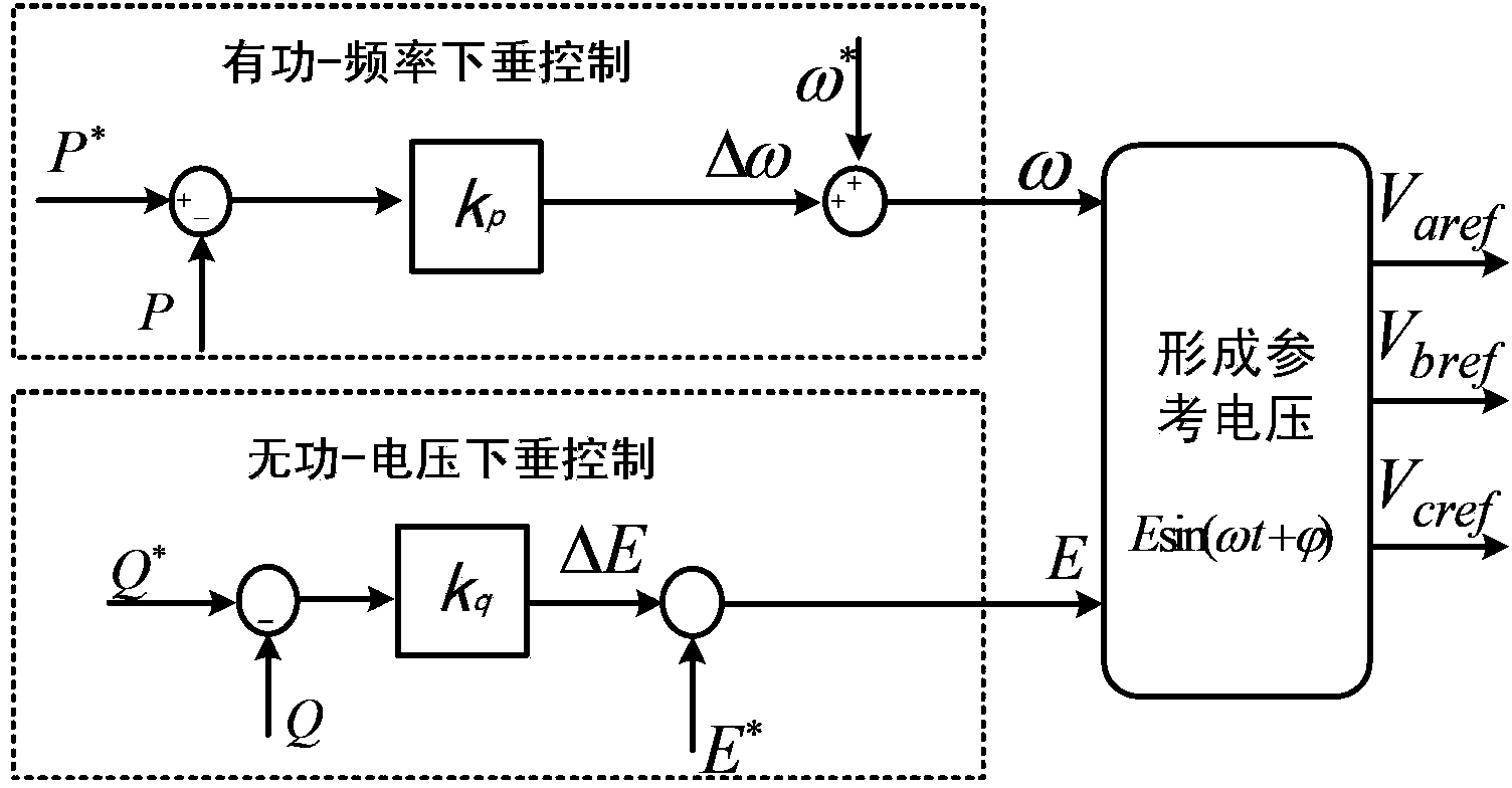
Figure 1 
Figure 2 
Figure 3
Abstract
Description
technical field
[0001] The invention relates to the field of inverter control and grid connection, in particular to a method for controlling an inverter in an energy storage unit to realize grid connection of a microgrid. Background technique
[0002] In the traditional power system, the grid-connection condition is that the power grid waiting for grid-connection and the power frequency grid meet the voltage amplitude difference, voltage phase angle difference, and frequency difference at both ends of the public coupling point within a certain range, ensuring There is no excessive inrush current, and after the grid-connection is closed, the power grid to be paralleled can quickly enter synchronous operation. However, the microgrid contains a large number of inverter power supplies and power electronic devices, resulting in weak inertia of the microgrid and weak anti-disturbance ability of the microgrid. When the above requirements are met, the voltage and power may fluctuate...
Examples
Embodiment Construction
[0022] see Figure 4 , the method of this embodiment based on the microgrid grid-connected control of the inverter in the energy storage unit is: before the microgrid is connected to the grid, all the inverter power supplies running in parallel adopt the droop control strategy, and the inverter power supply adopting the droop control strategy is The operation mode of peer-to-peer control is adopted. The micro-grid system adopts the operation mode of peer-to-peer control, which means that all inverters in the micro-grid system are equal in status; each inverter supplies power to the load according to the output capacity, and the output capacity is specific. is the droop gain coefficient in its droop control.
[0023] Droop control is as formula (1) and (2):
[0024] ω=ω * -k p (P-P * ) (1)
[0025] E=E * -k q (Q-Q * ) (2)
[0026] In formula (1) and formula (2), P * , Q * is the reference value of active power and reactive power; P and Q are the output values of ac...