Three-level three-phase half-bridge inverter circuit

An inverter circuit and three-phase half-bridge technology, which is applied to electrical components, AC power input to DC power output, output power conversion devices, etc., can solve the problems of large switching loss, low efficiency, and low capacity. Achieve the effects of reducing switching loss, high reliability, and easy expansion

Inactive Publication Date: 2014-01-15
710TH RES INST OF CHINA SHIPBUILDING IND CORP +1
View PDF4 Cites 5 Cited by
  • Summary
  • Abstract
  • Description
  • Claims
  • Application Information

AI Technical Summary

Problems solved by technology

[0002] The three-level three-phase half-bridge inverter circuit is aimed at the 300kW wave energy power generation system. After the offshore buoy converts the mechanical energy into electrical energy, it needs to use high DC voltage, generally above 1000V, for the long-distance transmission through the submarine cable, while the traditional The high-power conversion technology adopts high-power IGBT modules. When using high-frequency SPWM modulation control strategy, figure 1 It is an ordinary three-phase half-bridge inverter circuit. Since it works at high frequency throughout the entire cycle, there are problems of low efficiency and capacity increase due to large switching losses. Therefore, it is necessary to develop a new type of inverter circuit.

Method used


Image

  • Three-level three-phase half-bridge inverter circuit
  • Three-level three-phase half-bridge inverter circuit
  • Three-level three-phase half-bridge inverter circuit

Examples


Embodiment Construction

[0016] The present invention will be described in detail below with reference to the accompanying drawings and examples.

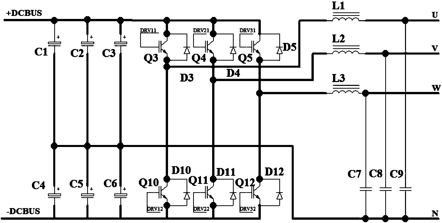
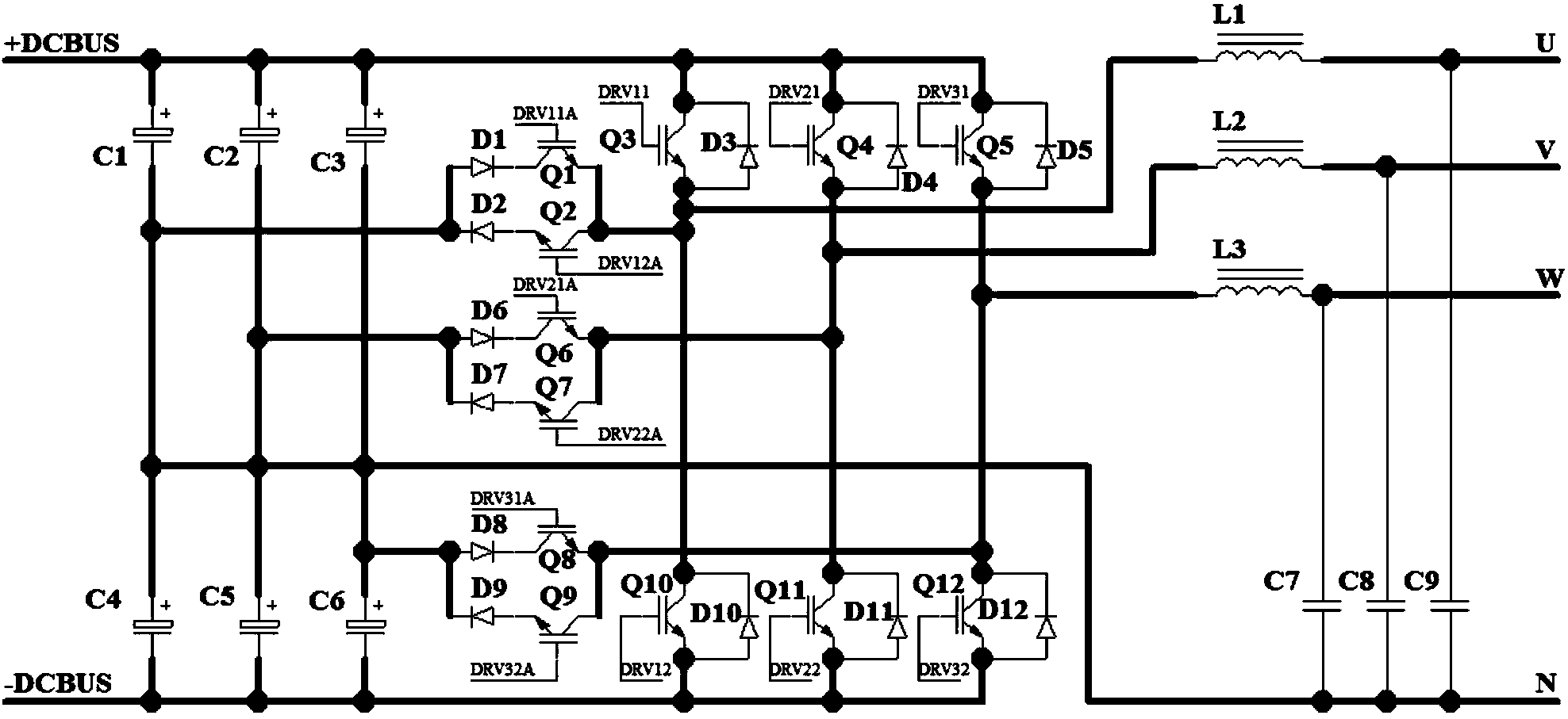
[0017] as attached figure 2 As shown, the present invention provides a three-level three-phase half-bridge inverter circuit, which can be split into three independent single-phase half-bridge circuits A, B, and C.

[0018] Single-phase half-bridge circuit A includes ionized electrolyte capacitors C1, C4, capacitor C9, diodes D1, D2, D3, D10, high-power switching tubes Q1, Q2, Q3, Q10, and inductor L1;

[0019] The positive pole of the ionizing electrolyte capacitor C1 is connected to the DC input +DCBUS, the negative pole of the ionizing electrolyte capacitor C1 is connected to the positive pole of the ionizing electrolyte capacitor C4, the negative pole of the ionizing electrolyte capacitor C4 is connected to the DC input-DCBUS, and the positive pole of the diode D1 is connected to the ionizing electrolyte capacitor C1 and the ionization Between the ele...


PUM


Abstract

The invention provides a three-level three-phase half-bridge inverter circuit. The three-level three-phase half-bridge inverter circuit comprises three same single-phase half-bridge circuits. Each single-phase half-bridge circuit comprises an ionization electrolyte capacitor C1, an ionization electrolyte capacitor C4, a capacitor C9, a diode D1, a diode D2, a diode D3, a diode D10, a high-power switching tube Q1, a high-power switching tube Q2, a high-power switching tube Q3, a high-power switching tube Q 10, and an electrical inductor L1. Based on a traditional three-phase inverter circuit topology, auxiliary access bridge arms at the follow current stage are added, and the upper bridge arm and the lower bridge arm work in the positive half period of sine waves and the negative half period of sine waves respectively. At the follow current stage, the auxiliary bridge arms are used and a low-frequency switch is adopted, so that switch consumption generated in a high-power inverter is effectively lowered. SPWM is adopted in the whole system, and the three-phase pure sine waves are output. By the adoption of the design of modularized parallel redundancy, the reliability is high and the fault of a single module cannot influence running of the system. In addition, the capacity can be increased and decreased according to needs, so that capacity enlargement is convenient. The three-phase-independent inverting method has excellent 100% unbalance load capacity. Besides, the system can provide single-phase alternating currents and three-phase alternating currents at the same time.

Description

technical field [0001] The invention relates to a three-level three-phase half-bridge inverter circuit, belonging to the technical field of power electronics. Background technique [0002] The three-level three-phase half-bridge inverter circuit is aimed at the 300kW wave energy power generation system. After the offshore buoy converts the mechanical energy into electrical energy, it needs to use high DC voltage, generally above 1000V, for the long-distance transmission through the submarine cable, while the traditional The high-power conversion technology adopts high-power IGBT modules. When using high-frequency SPWM modulation control strategy, figure 1 It is an ordinary three-phase half-bridge inverter circuit. Because it works at high frequency throughout the entire cycle, it has the problems of low efficiency and low capacity due to large switching losses. Therefore, it is necessary to develop a new type of inverter circuit. Contents of the invention [0003] In view...

Claims


Application Information

Patent Timeline
Patent Type & Authority Applications(China)
IPC IPC(8): H02M7/483H02M7/5387
Inventor 王同春戚战峰寿丽莉岳孝磊杨勇李新会康玲
Owner 710TH RES INST OF CHINA SHIPBUILDING IND CORP
Why Eureka
Try Eureka