
Novel abdominal distension treatment device for department of gastroenterology
A treatment device and gastroenterology technology, applied in physical therapy, massage belts, massage combs, etc., can solve the problems of inability to meet the needs of patients, inconvenience in moving massage back and forth, inconvenient pressing up and down massage, etc., to improve massage efficiency, Meet the needs of use, the effect of convenient operation
Patent Information
- Authority / Receiving Office
- CN · China
- Patent Type
- Applications(China)
- Current Assignee / Owner
- Publication Date
- 2019-03-08
Smart Images
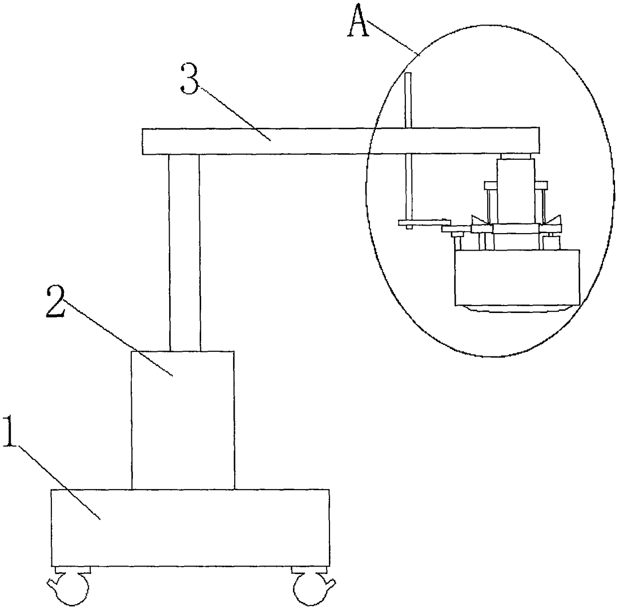
Figure 1 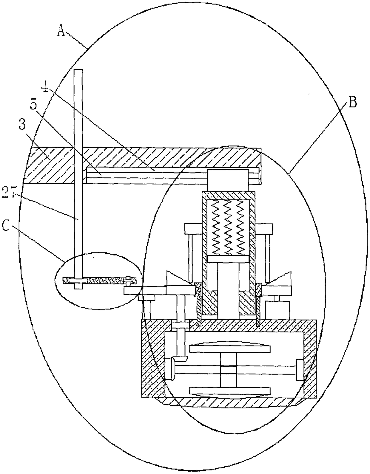
Figure 2 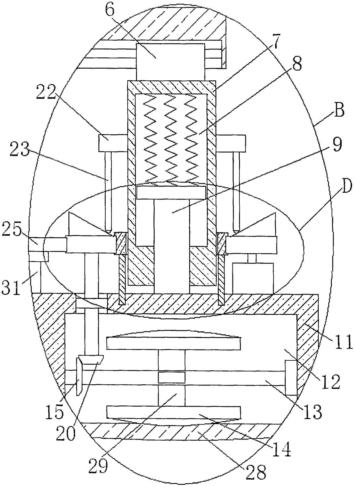
Figure 3
Abstract
Description
technical field
[0001] The invention relates to the technical field of abdominal distension treatment equipment, in particular to a novel abdominal distension treatment device used in gastroenterology. Background technique
[0002] Gastroenterology is a third-level clinical discipline that mainly studies diseases of the esophagus, stomach, small intestine, large intestine, liver, gallbladder, and pancreas. It is caused by the lack of activity of the stomach caused by time inactivity. After retrieval, the authorized announcement number CN107536700A discloses an abdominal distension auxiliary treatment device for gastroenterology, including a chassis, an electric push rod, a bracket, a rotating sleeve, a bearing, a rotating rod, Handle, cover, infrared heating lamp, temperature measuring instrument, motor, rotating shaft, rotating plate, elastic pad, first mounting hole, second mounting hole, protective belt, hanging ring, hook, which are used for adjuvant treatment of abdomin...
Examples
Embodiment
[0027] refer to Figure 1-5, the present embodiment proposes a novel abdominal distention treatment device for gastroenterology, comprising a base 1, a push rod motor 2 is fixedly mounted on the top of the base 1, and a top plate 3 is fixedly mounted on the output shaft of the push rod motor 2, and the top plate 3 One side of the bottom of the bottom is provided with a first chute 4, and the same positioning rod 5 is fixedly installed on the inner walls of both sides of the first chute 4, and the sliding sleeve on the positioning rod 5 is provided with a sliding seat 6, and the bottom of the sliding seat 6 Extend to the bottom of top plate 3 and be fixedly installed with support bar 7, begin to have cavity 8 on support bar 7, and be provided with vertical bar 9 in cavity 8, the top of vertical bar 9 is fixedly installed with cavity 8 slidingly installed A horizontal plate 10, and a plurality of springs are welded between the top of the horizontal plate 10 and the top inner wal...