
Method and system for obstacle avoidance for a vehicle
a technology for vehicles and robots, applied in the direction of navigation instruments, process and machine control, instruments, etc., can solve the problems of prone to delayed reaction or indecisiveness of reactive obstacle detection systems, and the likelihood of a collision may increase markedly
Patent Information
- Authority / Receiving Office
- US · United States
- Patent Type
- Applications(United States)
- Current Assignee / Owner
- Publication Date
- 2009-04-09
- Estimated Expiration
- Not applicable · inactive patent
Smart Images
Figure 1 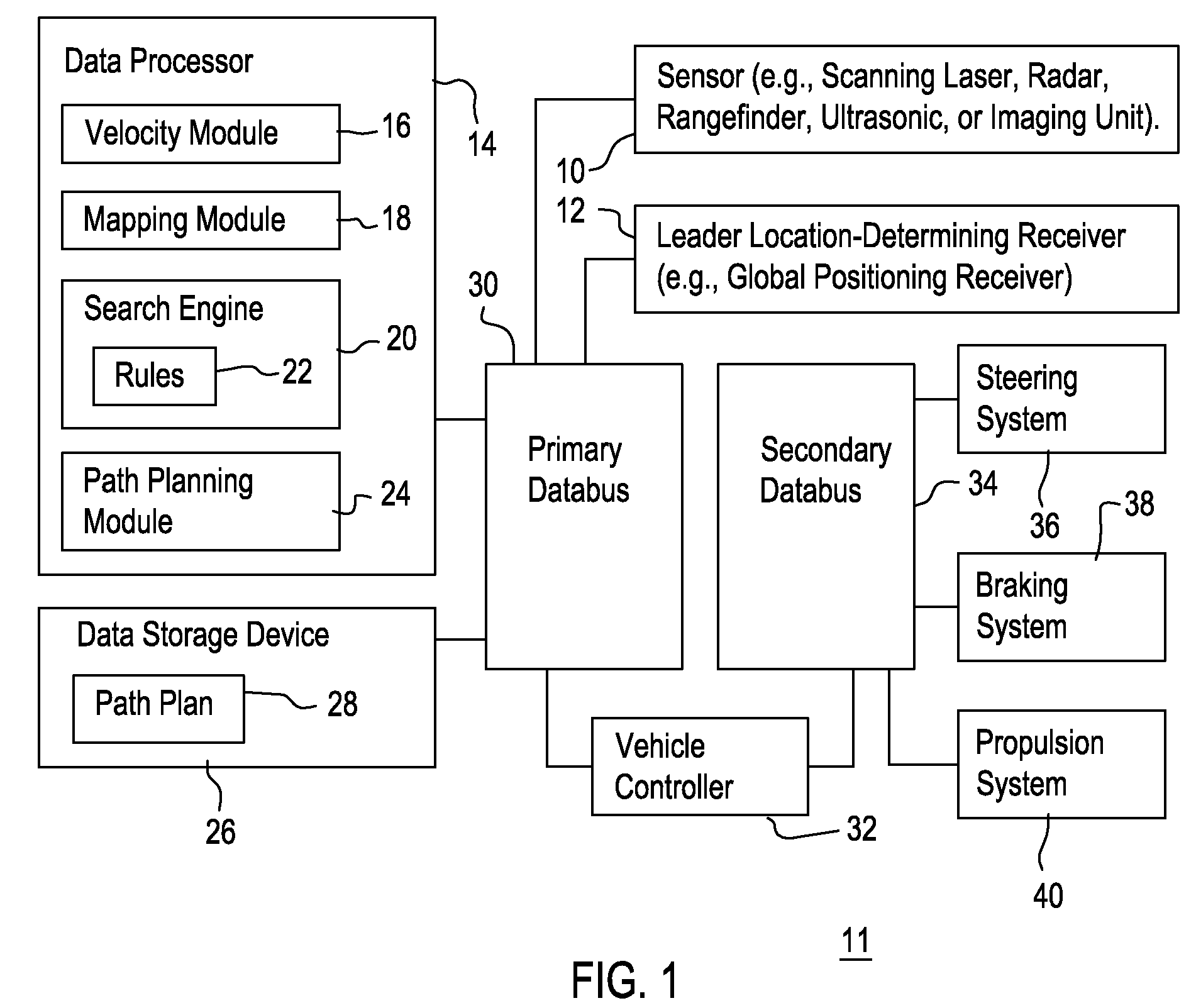
Figure 2 
Figure 3
Abstract
Description
FIELD OF THE INVENTION
[0001] This invention relates to a method and system for obstacle avoidance for a vehicle or robot.BACKGROUND OF THE INVENTION
[0002] Obstacle avoidance systems may be used to augment the performance of human operators of vehicles or for autonomous or unmanned vehicles. A reactive obstacle avoidance system may use local data of a vehicular environment to generate a control output for steering a vehicle to avoid an obstacle. However, a reactive obstacle detection system may be prone to delayed reaction or indecisiveness when computations approach boundaries, discontinuities, local maxima, or local minima. If a vehicle is presented with an obstacle directly in its path of travel, and the obstacle detection algorithm struggles with the computations associated with boundaries, discontinuities, local maxima, or local minima, the likelihood of a collision may increase markedly. Thus, there is need to expedite the search or solution for a suitable obstacle avoidance path...
Examples
Embodiment Construction
[0007]FIG. 1 illustrates one possible embodiment for the obstacle avoidance system 11. An obstacle is a stationary object, a mobile object, or another object that occupies a spatial location that is directly or indirectly between a vehicle at an origination position (e.g., origination coordinates) and a destination position (e.g., destination coordinates). The obstacle avoidance system 11 comprises a sensor 10, a location-determining receiver 12, a data processor 14 and a data storage device 26 coupled to a primary databus 30. The primary data bus 30 is coupled to a vehicle controller 32.
[0008]A secondary databus 34 is coupled to the vehicle controller 32. Although the steering system 36, a braking system 38, and a propulsion system 40 are coupled to the secondary databus 34 as shown in FIG. 1, in another embodiment the steering system 36, the braking system 38, and the propulsion system 40 may be coupled to the vehicle controller 32 via one or more transmission lines.
[0009]The data...