
Phase selection programmable frequency divider
A phase selection and frequency divider technology, applied in the field of frequency synthesizers, can solve the problems of limited frequency accuracy, logic errors, glitches, etc., to improve the overall phase noise, reduce in-band phase noise, and reduce the probability of errors.
Patent Information
- Authority / Receiving Office
- CN · China
- Patent Type
- Applications(China)
- Current Assignee / Owner
- Publication Date
- 2009-03-04
- Estimated Expiration
- Not applicable · inactive patent
Smart Images
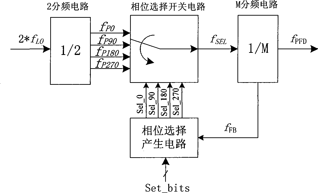
Figure 1 
Figure 2 
Figure 3
Abstract
Description
technical field
[0001] The invention relates to a frequency synthesizer based on a phase-locked loop, in particular to a phase selection programmable frequency divider in the frequency synthesizer based on a phase-locked loop. Background technique
[0002] As we all know, the programmable frequency divider is one of the components of the frequency synthesizer based on the phase-locked loop structure. The frequency synthesizer is widely used in receivers to generate local oscillator signals or in transmitters to generate carrier frequency signals. vibration signal.
[0003] Existing programmable frequency dividers are mainly integer frequency dividers (integer-N) whose minimum frequency division can only be integers and fractional frequency dividers (fractional-N) that use retiming (retiming) to control phase selection, but this Both programmable frequency dividers have certain disadvantages. Among them, there are two potential problems in the phase-locked loop structure us...
Examples
Embodiment Construction
[0015] In one embodiment, such as figure 1 As shown, the phase selection programmable frequency divider of the present invention includes a 2 frequency division circuit, a phase selection switch circuit, a phase selection generation circuit and an M frequency division circuit.
[0016] The 2 frequency division circuit is a 2 frequency division circuit with orthogonal output characteristics. In the present invention, the frequency of the input signal of the 2 frequency division circuit is 2 times the actual operating frequency of the system, i.e. 2*f L0 , its output signal is four signals f with a phase difference of 90 degrees P0 , f P90 , f P180 and f P270 , those skilled in the art should know that the frequencies of these four output signals are the same as the actual working frequency of the system.
[0017] The phase selection switch circuit is used to select and output one of the four signals with a phase difference of 90 degrees under the control of the switching co...