
Linear and curvilinear motor system
A straight-curve motion and motor technology, applied in the field of straight-curve motion motor systems, can solve the problems of not having Hall sensors, smooth sliding, and precise positioning, and achieve the effect of positioning and precise positioning
Patent Information
- Authority / Receiving Office
- CN · China
- Patent Type
- Applications(China)
- Current Assignee / Owner
- Publication Date
- 2011-03-30
- Estimated Expiration
- Not applicable · inactive patent
Smart Images
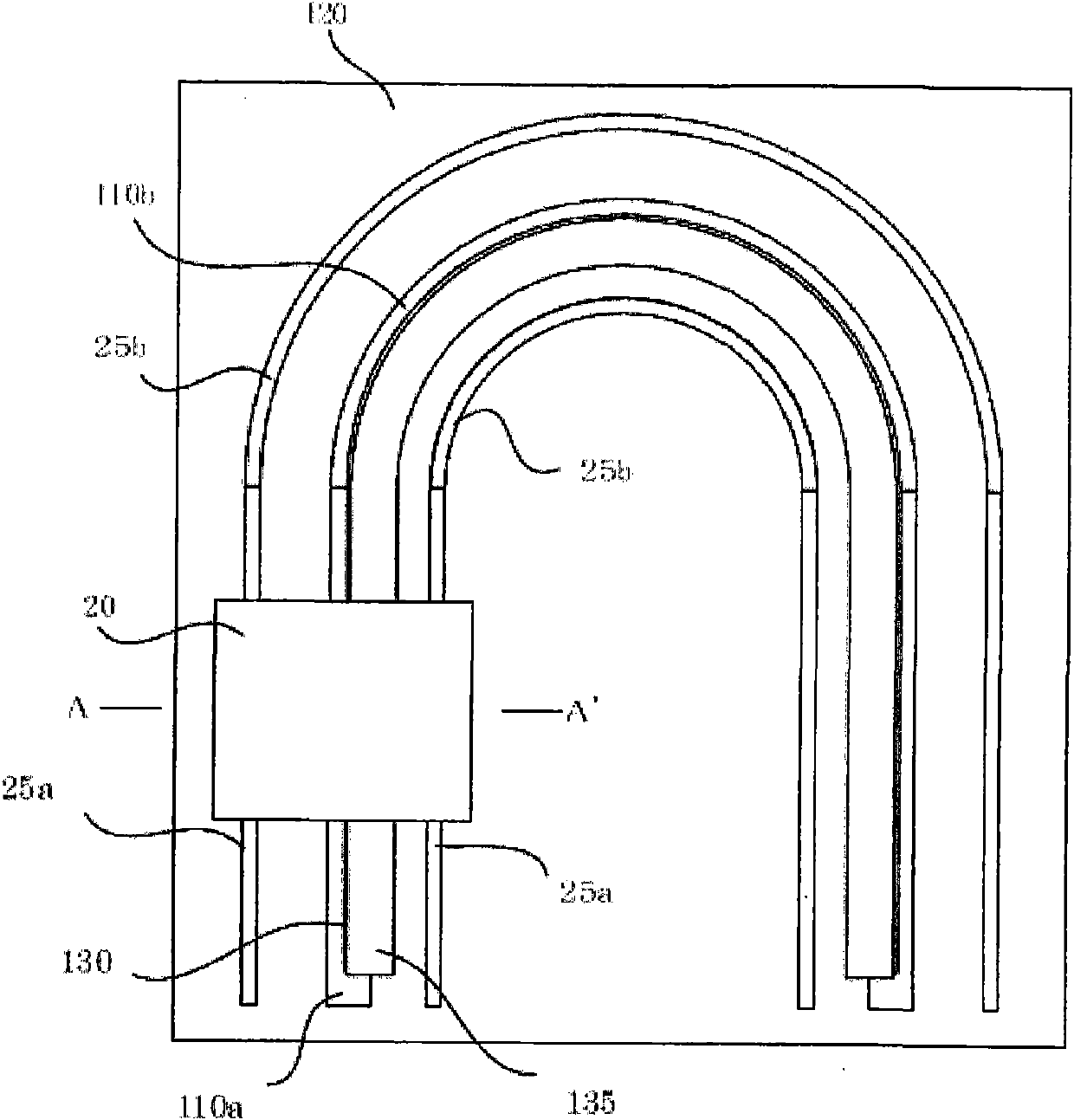
Figure 1 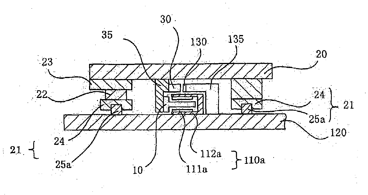
Figure 2 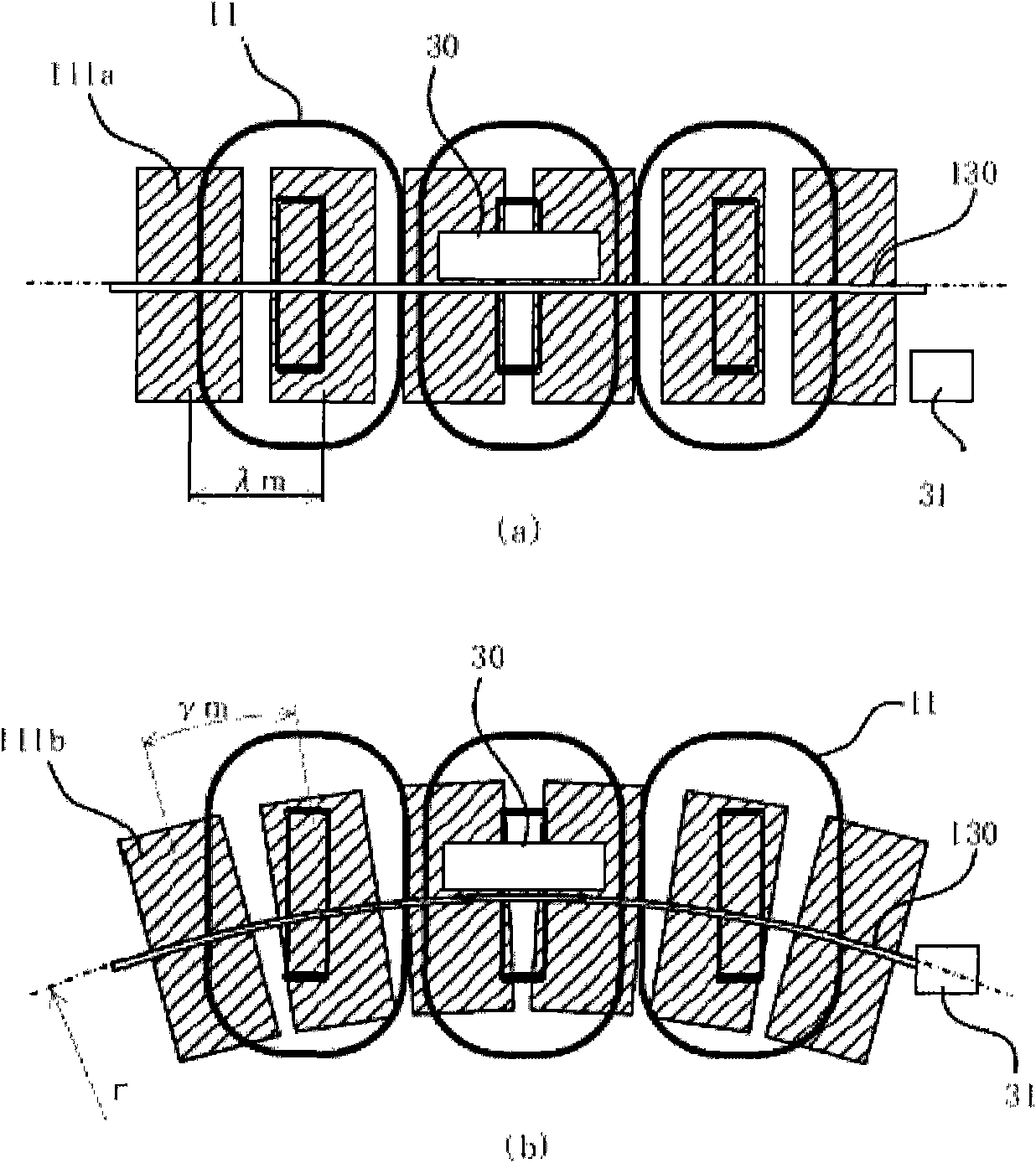
Figure 3
Abstract
Description
technical field
[0001] The present invention relates to a linear-curve motor system, which is used as a positioning device mounted on a semiconductor manufacturing device, a liquid crystal manufacturing device, etc., and enables a slide table to slide smoothly along a straight-curve guide device composed of a linear track and a curved track. , and achieve precise positioning. Background technique
[0002] Conventionally, as a straight-curve motor system used as a positioning device mounted on a semiconductor manufacturing device, a liquid crystal manufacturing device, etc., a system has been proposed in which a mover generates thrust against a stator having a linear portion and an arc portion, and the mover is It can slide on a straight-curved guide having a guide rail composed of a linear track and a curved track (for example, refer to Patent Documents 1 and 2).
[0003] In the linear motion motor system described above, the mover is constituted only by the linear portion,...
Examples
Embodiment 1
[0047] figure 1 It is a plan view showing the overall structure of a linear-curve motor system commonly used in this embodiment, figure 2 yes figure 1 The A-A' section view. image 3 It is a diagram of the common winding, permanent magnet, scale, encoder head, and hall sensor arrangement in this embodiment viewed from above, (a) is a diagram illustrating the state when a linear rail slides, and (b) is a diagram illustrating a circle Diagram of the state when the arc track slides.
[0048] Figure 4 It is a perspective view of the slide table based on the straight-curve motor system of the first embodiment viewed from above, (a) is a diagram illustrating a state when sliding on a linear track, and (b) is a diagram illustrating a state when sliding on an arcuate track .
[0049] figure 1 The linear-curve motor system shown is a track in which a 180-degree arc track is connected between two parallel linear tracks. in the above Figure 1 to Figure 3 Among them, 120 is a...
Embodiment 2
[0069] Figure 5 It is a perspective view of the slide table which shows the structure of 2nd Embodiment seen from above, (a) is a figure explaining the state when linear track sliding, (b) is a figure explaining the state when circular arc track sliding.
[0070] The second embodiment differs from the first embodiment in that the numbers of straight-bending guides 21 , swivel guides 22 , and slide table guides 23 are different. In addition, position detection devices 30 , 31 are disposed between the pair of right and left straight bending guide devices 21 .
[0071] Specifically, the second embodiment is characterized in that K (K is an odd number of 3 or more) sliders of straight-bending guide devices are provided on the lower part of the slide table, and K-1 slide blocks are respectively provided between the slide table and the slide table. There are: sliding table guiding device, which has a mechanism to move the sliding table in the direction perpendicular to the linear ...
Embodiment 3
[0076] Image 6 It is a perspective view of the slide table showing the structure of the third embodiment seen from above, (a) is a diagram illustrating a state when sliding on a linear track, and (b) is a diagram illustrating a state when sliding on an arcuate track.
[0077] The third embodiment differs from the first embodiment and the second embodiment in that the number of straight-curve guides 21 , rotary guides 22 , and slide table guides 23 is different. In addition, position detection devices 30 , 31 are disposed between the pair of right and left straight bending guide devices 21 .
[0078] Specifically, the third embodiment is characterized in that K (K is an even number equal to or greater than 2, in this example, K=2) sliders 24 of the straight-bending guide device 21 are respectively provided on the left and right lower parts of the slide table 20, Between the slide block 24 and the slide table 20, the first rotary guide device 22 is arranged on one side of the ...