
Controllable multi-pulse gas generator
A gas generation and multi-pulse technology, which is applied in the direction of production fluid, wellbore/well components, earthwork drilling and production, etc., can solve problems such as difficult closure, delay closure time and facilitate construction progress
Patent Information
- Authority / Receiving Office
- CN · China
- Patent Type
- Patents(China)
- Current Assignee / Owner
- Publication Date
- 2016-07-20
- Estimated Expiration
- Not applicable · inactive patent
Smart Images
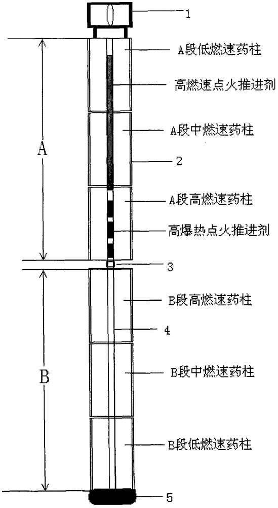
Figure 1
Abstract
Description
technical field
[0001] The invention belongs to the technical field of gas generating devices, and relates to a novel controllable multi-pulse gas generating device for high-energy gas fracturing, which can be used for oilfield development and improve crude oil recovery. Background technique
[0002] As a measure for oilfield development and production stimulation, high-energy gas fracturing technology has the advantages of simple construction, low cost, and quick results. High-energy gas is usually generated after combustion of composite solid propellant or double-base drug. Since composite solid propellant has better temperature resistance and higher energy, it is the first choice for implementing this measure. When the geological conditions are suitable for this measure, a certain amount of composite solid propellant is ignited in the operating part of the oil well or water injection well, and the high-temperature and high-pressure gas produced will act to form multiple r...
Examples
Embodiment Construction
[0011] Such as figure 1 As shown, the device of the present invention is composed of an igniter 1, a section A high-alumina and high-chlorine propellant grain, a B-section high-alumina and high-chloride propellant grain, a plugging joint 3, and a centralizer 5. The high-alumina and high-chlorine propellant grains in sections A and B are each Φ84×3000mm, and the plugging joint 3 is used to ensure that the high-temperature and high-pressure airflow after the ignition propellant in the center tube 4 of section A will not leak into the center tube 4 of the grain column in section B. Ensure that the A-stage high-alumina and high-chlorine propellant grains burn first, and the B-stage high-burning-rate propellant grains burn later, so as to form more pressure pulses, that is, the number of pulses is controllable. The centralizer 5 is used to ensure that the shell of the drug column is not damaged by casing wall friction during the whole device going downhole. Φ86×50mm.
[0012] The ...