
Dynamic controller of hinge-free aircraft
An aircraft and controller technology, applied in the aerospace field, can solve the problems of small size, air breakdown, complex and bulky mechanism at the trailing edge of the aircraft, achieve small flight weight and fuel consumption, reduce suction load, and large cavity volume. Effect
Patent Information
- Authority / Receiving Office
- CN · China
- Patent Type
- Patents(China)
- Current Assignee / Owner
- Publication Date
- 2013-12-04
- Estimated Expiration
- Not applicable · inactive patent
Smart Images
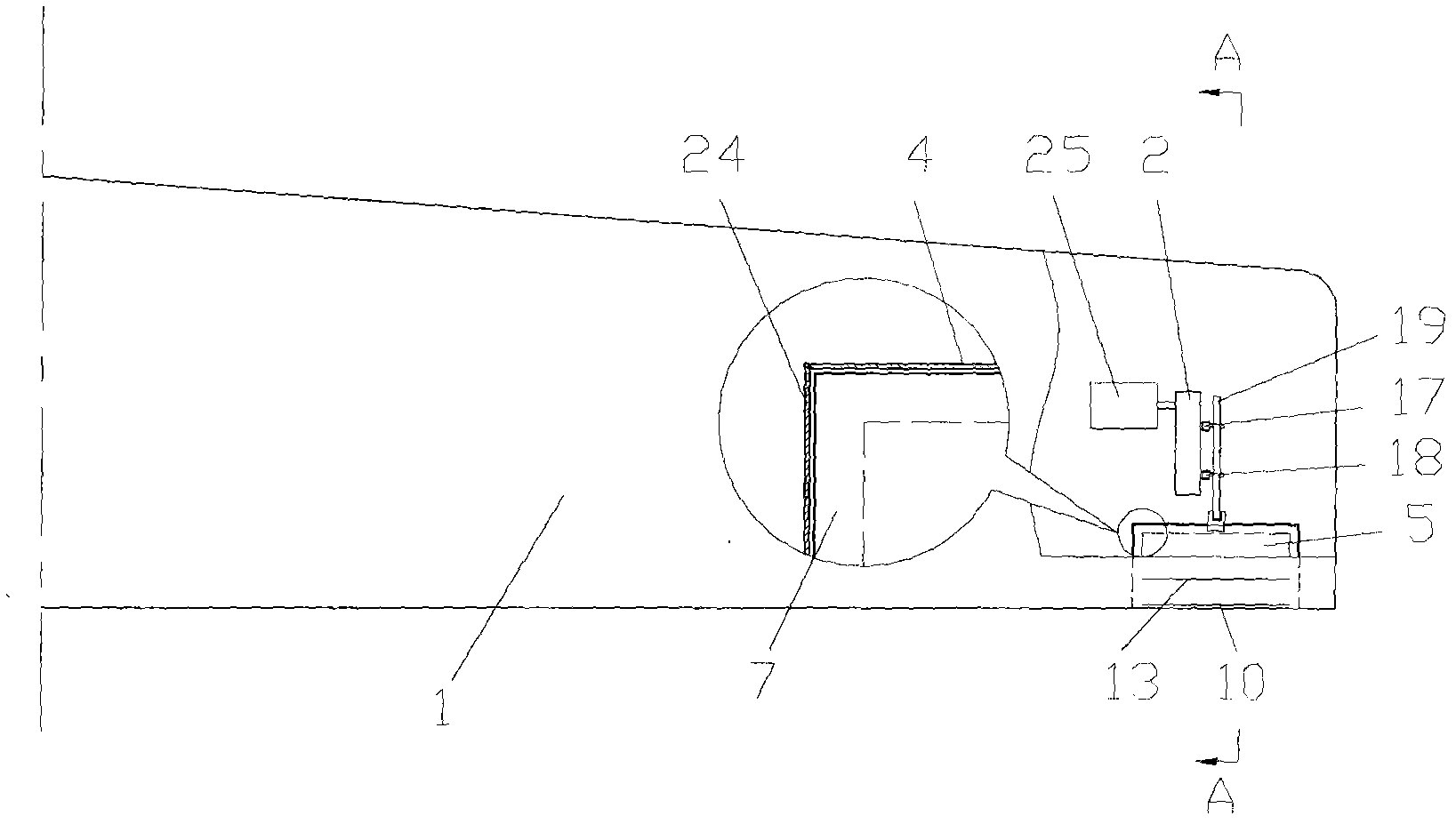
Figure 1 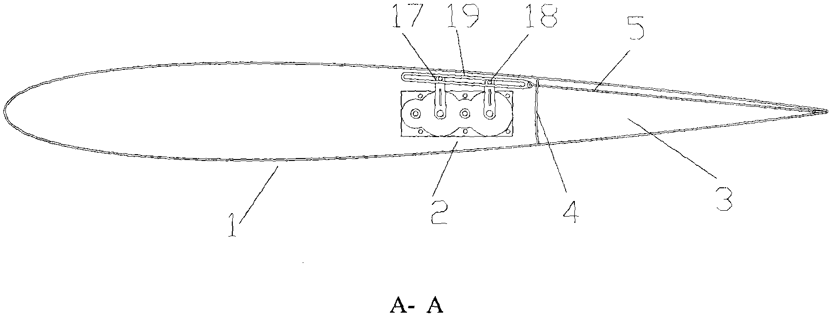
Figure 2 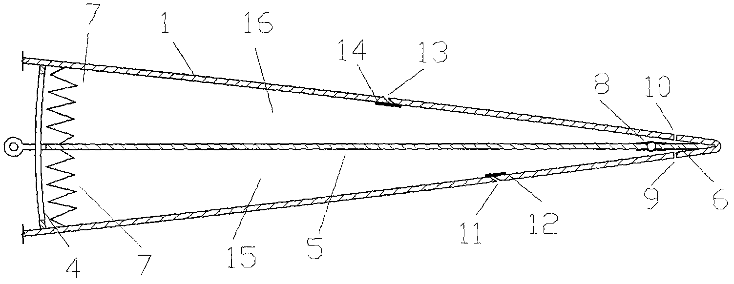
Figure 3
Abstract
Description
technical field
[0001] The invention relates to the field of aerospace, in particular to an aircraft dynamic control device. Background technique
[0002] The dynamic control of the aircraft is the control of the flight attitude of the aircraft such as pitch angle, sideslip angle and roll angle. At present, the more mature control methods are: pneumatic rudder surface control, gas rudder surface control and thrust vector control. Aerodynamic rudder surface control is to set ailerons on the wings and rely on the deflection of the aileron surface to achieve the control purpose. The advantage is that it is convenient and flexible to control, but the disadvantage is that hinges need to be set on the wings, and a hydraulic transmission device or an electric transmission device is required, so the whole mechanism is complicated and heavy. Gas rudder surface technology and thrust vectoring technology are widely used in rockets and missiles, and are also used in some fighter jets ...
Examples
Embodiment Construction
[0033] The present embodiment is two hingeless aircraft controllers, which are respectively located in the wings on both sides of the aircraft. This embodiment only describes the hingeless aircraft controller in one side of the wing.
[0034] Present embodiment takes the long straight wing of NACA0012 symmetrical airfoil as carrier.
[0035] This embodiment includes a fluidic cabin body 3 , a fluidic mechanism, a transmission mechanism 2 and a motor 25 . Wherein, the jet mechanism is located at the tail edge of the wing where the jet mechanism is located in the jet cabin 3, its spanwise position is 75%-95% away from the wing root, and its chordwise position is 73%-100% of the wing chord length. The transmission mechanism 2 and the motor 25 are located in the wing and outside the jet cabin body 3 . The motor 25 drives the rotary plate 5 of the jet mechanism 3 to move up and down through the transmission mechanism 2 . Upper jet slots 10 and lower jet slots 9 are distributed a...