
Long-stroke linear permanent magnet motor operation mechanism of high-voltage breaker
A high-voltage circuit breaker and operating mechanism technology, applied in the field of high-voltage circuit breaker long-stroke linear permanent magnet motor operating mechanism, can solve the problem that it is difficult to meet the long-stroke opening and closing operation requirements of high-voltage circuit breakers, the opening and closing operation is difficult to guarantee, and the permanent magnet The short stroke of the mechanism can reduce the risk of irreversible demagnetization, improve the torque density, and achieve the effect of strong magnetic concentration effect
Patent Information
- Authority / Receiving Office
- CN · China
- Patent Type
- Applications(China)
- Current Assignee / Owner
- Publication Date
- 2011-08-17
Smart Images
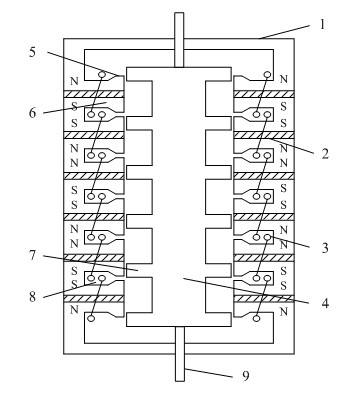
Figure 1 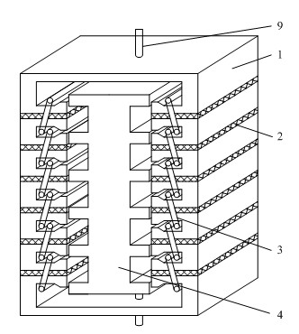
Figure 2 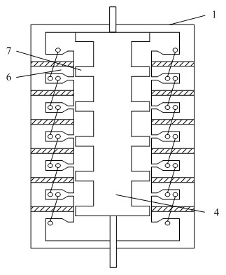
Figure 3
Abstract
Description
technical field
[0001] The invention belongs to the technical field of switchgear in electrical engineering, and in particular relates to an operating mechanism of a long-stroke linear permanent magnet motor for a high-voltage circuit breaker. Background technique
[0002] The operating mechanisms of traditional high-voltage circuit breakers mainly include hydraulic mechanisms, pneumatic mechanisms, spring mechanisms and electromagnetic mechanisms. The hydraulic operating mechanism has a series of advantages such as high energy intensity, fast response, low noise, and reliable action. The pneumatic operating mechanism uses compressed air as an energy source to generate thrust, and does not require high-power DC power supply or laying control cables. Pneumatic and hydraulic systems can meet the long-stroke and high-power operation requirements, and are mainly used in high-voltage circuit breakers with high voltage levels. However, the system is complex and the reliability is ...
Examples
Embodiment Construction
[0020] The present invention will be further described below in conjunction with accompanying drawing.
[0021] Depend on figure 1 It can be seen that an operating mechanism of a long-stroke linear permanent magnet motor for a high-voltage circuit breaker includes a stator core 1, a mover core 4, a driving rod 5, and a permanent magnet 2. The stator core 1 is a box body, and the mover core 4 is placed In the stator core 1, the drive rods 5 arranged at both ends of the mover core 4 pass through the casings at both ends of the stator core 1 and can move up and down. The inner side wall of the stator core 1 is provided with a stator salient pole 6, and the inside of the stator salient pole The permanent magnet 2 is set, and the polarities of the upper and lower adjacent permanent magnets are opposite, that is, the polarities of the opposite surfaces of the upper and lower adjacent permanent magnets are the same, as figure 1 As shown in , the upper and lower permanent magnets a...