
A DC high-voltage power supply control method and power supply device
A technology of DC high voltage power supply and power supply device, which is applied in the direction of high-efficiency power electronic conversion, control/regulation system, output power conversion device, etc., can solve the problems of wasting energy, low oscillation frequency, large transformer volume, etc. The effect of high, high oscillation frequency and high integration
Patent Information
- Authority / Receiving Office
- CN · China
- Patent Type
- Applications(China)
- Current Assignee / Owner
- Publication Date
- 2011-12-28
- Estimated Expiration
- Not applicable · inactive patent
Smart Images
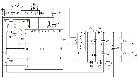
Figure 1 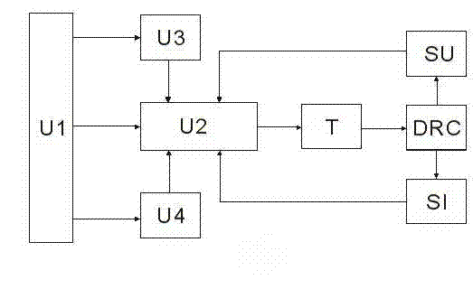
Figure 2 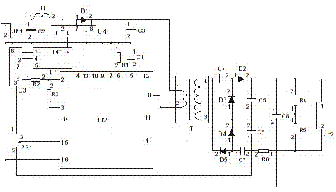
Figure 3
Abstract
Description
technical field
[0001] The invention belongs to the technical field of power electronic control, and is a DC high-voltage power supply control method and a power supply device applied in the fields of field radioactive instrument technology and nuclear technology application in the field of resource and environmental exploration technology. Background technique
[0002] In recent decades, the rapid development of computer technology and electronic technology, especially the continuous improvement of the performance of intelligent control chips and the continuous decline of prices, has led to the rapid development of radioactive instruments and technology, and is developing in the direction of intelligence and digitization. As radioactive instruments used in the field and outdoors, they are powered by batteries, so the power consumption of the instrument is a major research issue for modern instruments, and the DC high-voltage power supply device in the radioactive instrum...
Examples
Embodiment 1
[0020] Embodiment 1: Embodiment 1 is further described in conjunction with accompanying drawing:
[0021] Such as figure 1 The circuit diagram of the DC high-voltage power supply device shown: Pin 1 of the battery input connector (JP1) is connected to pin 1 of the inductance coil (L1) and pin 1 of the second capacitor (C2), and pin 2 of the battery input connector (JP1) Pin 2 of the second capacitor (C2), pin 6 of the digital potentiometer chip DS1804 (U3), pin 6 of the power management chip MAX761 (U4), pin 1 of the first resistor (R1), and the third Pin 2 of the capacitor (C3), pin 1 of the first capacitor (C1), pin 7, 9, 10, 13, 16 of the pulse width modulation control chip TL594 (U2), pin 1 of the sixth resistor (R6) , pin 2 of the eighth capacitor (C8), pin 2 of the fifth resistor (R5), and pin 2 of the high-voltage output connector (JP2); pin 2 of the inductance coil (L1) is connected to the first diode (D1 ) is connected to pin 1 and pin 2 and pin 7 of the power manag...