
Laser scanning sampling device using paraboloid mirror for correcting scanning angles
A parabolic mirror, correction scanning technology, applied in optics, optical components, instruments, etc., can solve the problems of reducing the effective utilization rate of the laser, the first shortcoming is not improved, and the processing difficulty is very high, and achieves low processing difficulty and simple structure. , the effect of easy maintenance
Patent Information
- Authority / Receiving Office
- CN · China
- Patent Type
- Applications(China)
- Current Assignee / Owner
- Publication Date
- 2013-05-08
- Estimated Expiration
- Not applicable · inactive patent
Smart Images
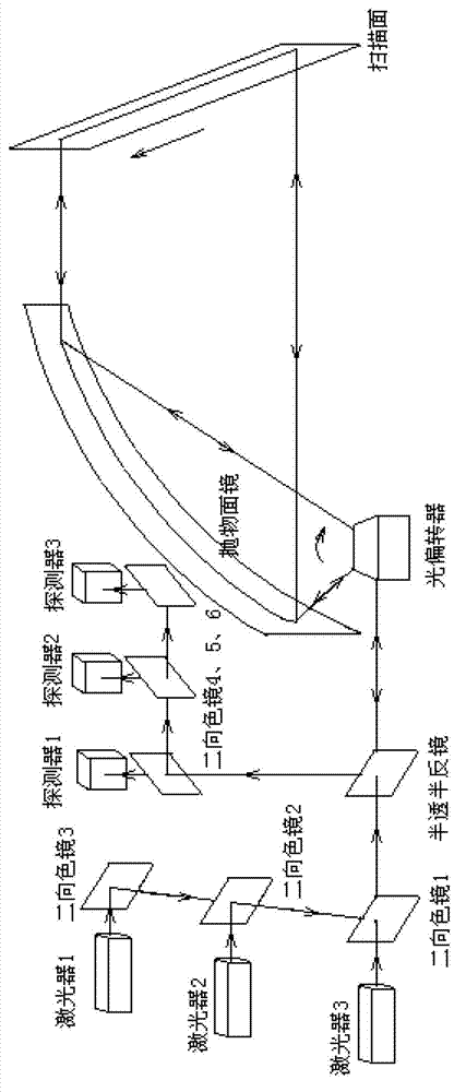
Figure 1 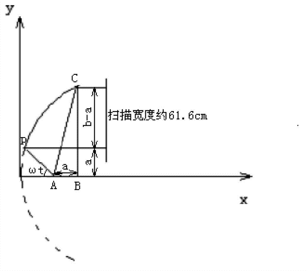
Figure 2 
Figure 3
Abstract
Description
technical field
[0001] The invention relates to a laser scanning sampling device, in particular to a laser scanning sampling device which uses a parabolic mirror to correct the scanning angle, uses an optical deflector to deflect the laser beam, and then reflects the scanning laser perpendicular to the scanning surface through the parabolic mirror; The light signal reflected by the scanning point at each moment is returned through the original light path, and finally sent to the detector group for reception. Background technique
[0002] With the rapid development of various laser spectroscopy technologies, laser scanning sampling technology has become increasingly mature and widely used in scanning imaging, image printing, projection, mineral detection, food testing and many other fields. At present, the commonly used laser scanning sampling technology uses semiconductor lasers. Through the design and construction of optical paths, it cooperates with optical deflection devi...
Examples
Embodiment
[0043] Such as figure 1As shown, a laser scanning sampling device using a parabolic mirror to correct the scanning angle includes a laser group, a dichroic mirror 3, 2, 1, a half mirror, a detector group, an optical deflector, a parabolic mirror, a dichroic Chromatic mirrors 4, 5, 6 and detectors 1, 2, 3. The laser group includes laser 1, laser 2 and laser 3 that emit red light, green light and blue light respectively. The laser light emitted by these lasers is combined by dichroic mirrors 3, 2 and 1 respectively and then emitted from dichroic mirror 1 to half-mirror, and then to the light deflector. The laser beam is deflected by the deflector to scan at a certain angle (50 degrees in this embodiment). These scanning lasers at different angles are reflected from the focus of the parabolic mirror, and after being reflected by the parabolic mirror, a parallel scanning laser is formed. Normal incidence to the scanning plane. The part of the mixed optical signal scattered at t...