
Magnetic-reaction brushless permanent magnet direct current motor
A DC motor, brushless permanent magnet technology, applied in the direction of electrical components, electromechanical devices, magnetic circuit static parts, etc., can solve the problems of small practical range, general effect, easy to burn, etc., to achieve enhanced safety, enhanced efficiency, Enhance the effect of driven couples
Patent Information
- Authority / Receiving Office
- CN · China
- Patent Type
- Applications(China)
- Current Assignee / Owner
- Publication Date
- 2013-09-25
- Estimated Expiration
- Not applicable · inactive patent
Smart Images
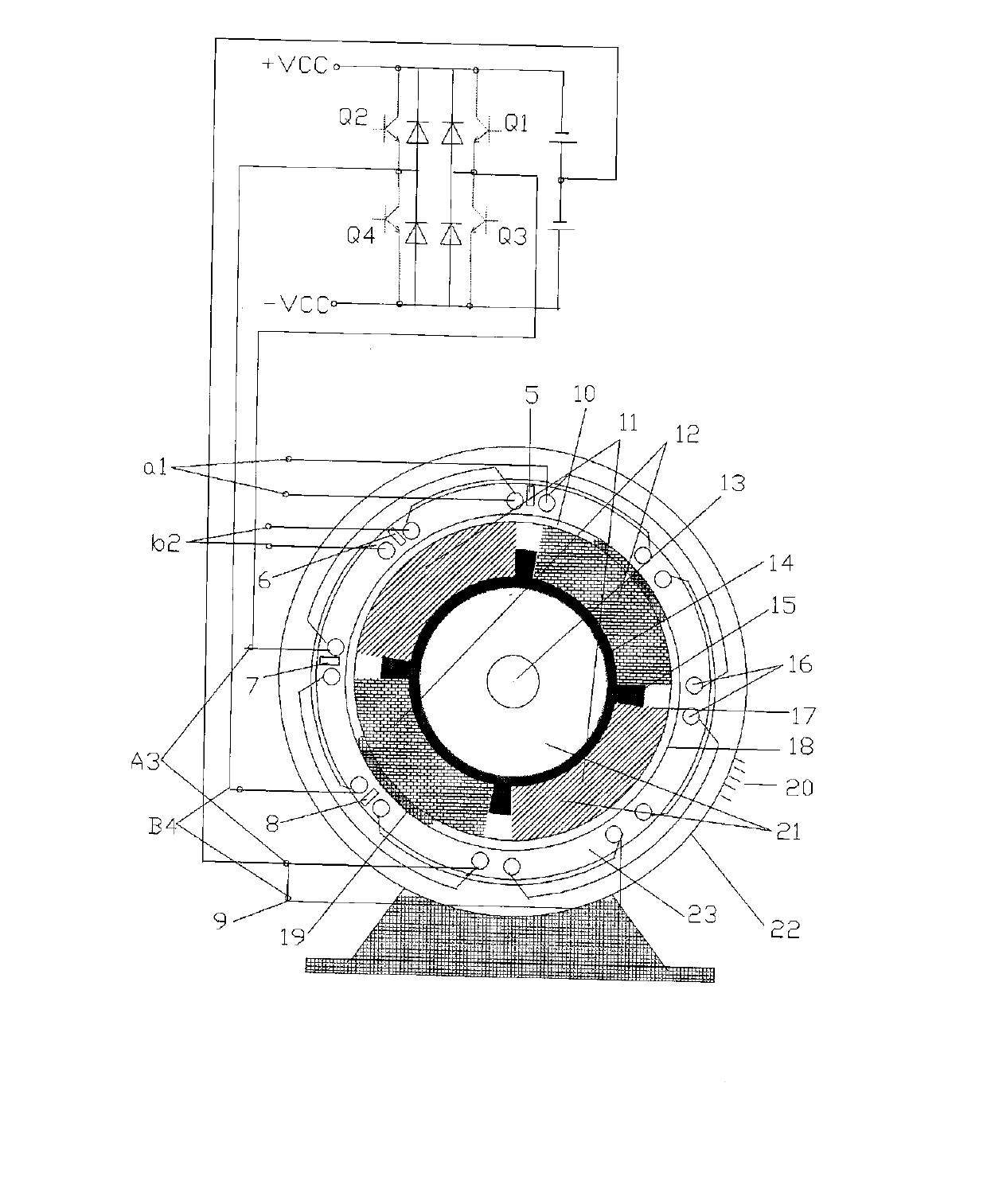
Figure 1 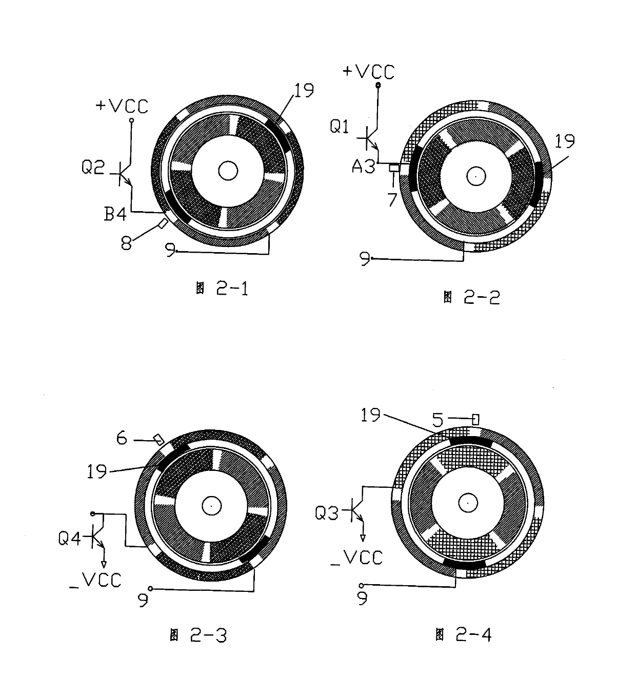
Figure 2 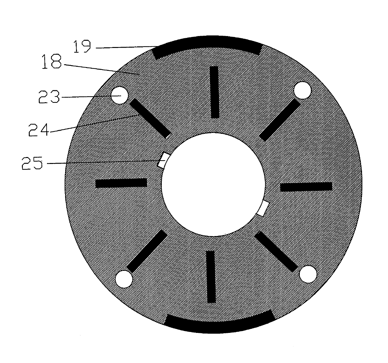
Figure 3
Abstract
Description
technical field
[0001] The project of the invention relates to the field of high-efficiency and energy-saving, specifically a high-efficiency and energy-saving motor, which combines the functions of motor, generator, servo motor, stepping motor, synchronous motor, etc., and is applicable to a wide range of magnetic response brushless permanent magnet DC motors. technical background:
[0002] The existing permanent magnet brushless DC motors all have the disadvantages of low efficiency, small practical range, average effect, and easy burning when the rotor is blocked. Invention content:
[0003] The purpose of the present invention is to overcome the defects of the prior art, and propose a high-efficiency energy-saving, wide application range, energy-saving and environmental protection; at the same time, it has the functions of motor, generator, servo motor, stepping motor, etc.; and the operating frequency can be adjusted freely, output Constant, no stalling and over-curre...
Examples
Embodiment Construction
[0029] Magnetic reaction permanent magnet brushless DC motor, taking a four-pole motor with a central shaft drive structure as an example; the stator structure includes a casing 22, a stator core 23, and cooling fins 20; two electromagnetic output windings A3 and B4, two a1, b2 small detection coil; magnetically shielded annular iron bracket 10, position magnetic identification devices 5, 6, 7, 8; permanent magnet rotor device 21 includes permanent magnets 11, 12, central shaft 13, rotor steel cylinder skeleton 14, and magnetic block positioning grid Bone 15; counterweight plate 18, indicating rotor magnetic protruding part 19, fastening screw hole 23, centrifugal fan blade 24, positioning pin groove 25; permanent magnet magnetic field line binding shielding sleeve 17, bearings and other components; dual power supply mode is adopted, Double bridge drive;
[0030] The principle of operation is now taking a motor driven by a four-pole central shaft and using a proximity switch a...