
A Method of Radio Frequency Vector Signal Synthesis
A vector signal and radio frequency signal source technology, applied in the field of signal processing, can solve the problems of difficult radio frequency segment vector synthesis, low phase accuracy, and low frequency upper limit, and achieve flexible adjustment methods, high precision, and improved common mode rejection ratio Effect
Patent Information
- Authority / Receiving Office
- CN · China
- Current Assignee / Owner
- Publication Date
- 2017-04-05
- Estimated Expiration
- Not applicable · inactive patent
Smart Images
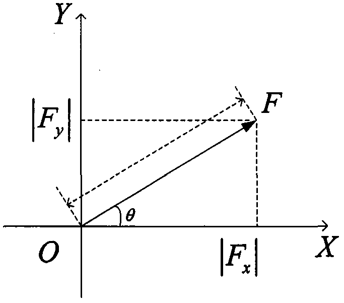
Figure 1 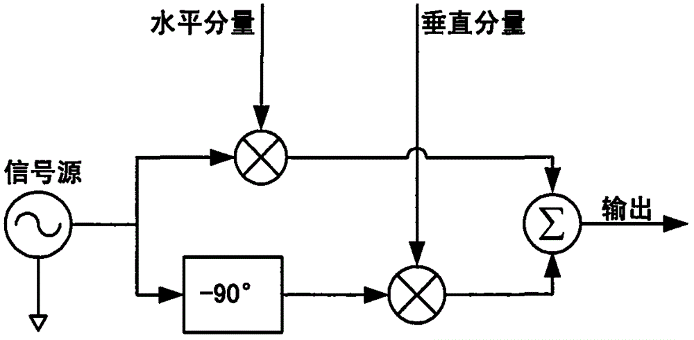
Figure 2 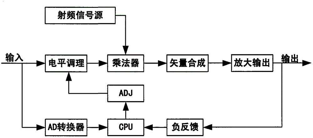
Figure 3
Abstract
Description
technical field
[0001] The invention relates to the technical field of signal processing, in particular to a method for synthesizing radio frequency vector signals. Background technique
[0002] Vector signal synthesis is one of the key technologies in the field of signal technology. Vector signal synthesizers are widely used in the development of electronic circuit systems and electronic products, and can be found in many modern electronic devices. figure 1 For vector illustration. Especially in the field of instrumentation and electronic measurement, the requirements for the frequency range, precision, stability and other parameters of the vector signal synthesizer are particularly high. Therefore, the vector signal synthesizer becomes the core of some measuring instruments.
[0003] Traditional vector synthesis methods, such as figure 2 As shown, it consists of a signal source, a 90° phase shifter, a mixer and an adder. In the horizontal component branch, the signal ...
Examples
Embodiment Construction
[0028] The present invention is described in further detail now in conjunction with accompanying drawing. These drawings are all simplified schematic diagrams, which only illustrate the basic structure of the present invention in a schematic manner, so they only show the configurations related to the present invention.
[0029] Step 1: Send the input to the CPU through the AD converter 1, and the CPU calculates its phase angle θ in , and store the amplitude and phase angle, and the CPU formulates an adjustment scheme to determine the value of the DA conversion module (ADJ);
[0030] The second step: the level adjustment module adds the horizontal component, the vertical component and the value of the DA conversion module (ADJ) and adjusts it, and outputs it to the multiplier after adjustment;
[0031] Step 3: The multiplier multiplies the output of the radio frequency signal source module and the output of the level conditioning module and sends the result to the orthogonal v...