
A horizontal ultrasonic paper thickness measuring device
An ultrasonic and thickness measuring technology, applied in measuring devices, using ultrasonic/sonic/infrasonic waves, instruments, etc., can solve the problems of reducing the service life of the paper shaft, affecting the normal operation of the equipment, and affecting the measurement accuracy, so as to improve the accuracy and disassemble. Simple and time-saving installation, the effect of high ultrasonic frequency
Patent Information
- Authority / Receiving Office
- CN · China
- Patent Type
- Patents(China)
- Current Assignee / Owner
- Publication Date
- 2016-06-22
- Estimated Expiration
- Not applicable · inactive patent
Smart Images
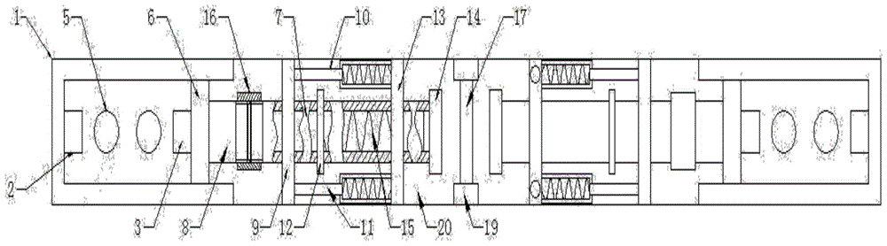
Figure 1 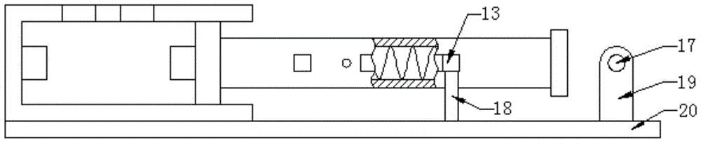
Figure 2 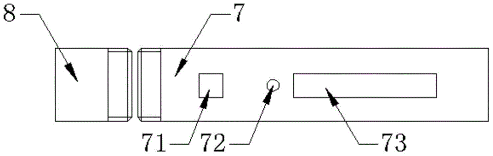
Figure 3
Abstract
Description
technical field
[0001] The invention relates to the field of ultrasonic ranging, in particular to a horizontal ultrasonic paper thickness measuring device for measuring the thickness of paper. Background technique
[0002] Among the products of paper thickness measurement, products using the contact measurement principle have the following advantages: contact measurement makes the paper in a compressed state during measurement, which reduces the adverse effects of the unevenness of the paper itself on the measurement results, and eliminates the need for paper Interference in the air gap. However, there are also disadvantages: in the case of the presence of a paper reel, the thickness measuring device will often cause an impact on the paper reel during work. Although the impact force is small, it is easy to make the paper reel Deformation will reduce the service life of the winding shaft, affect the final measurement accuracy, and affect the normal operation of the equipment...
Examples
Embodiment Construction
[0023] The present invention will be described below in conjunction with specific examples and accompanying drawings.
[0024] The horizontal ultrasonic paper thickness measuring device (thickness measuring device for short) of the present invention comprises a left measuring part and a right measuring part. The measuring part on the left side includes tank body 1, left ultrasonic probe 2, right ultrasonic probe 3, ventilation tube 5, piston 6, right cylindrical tube 7, left cylindrical tube 8, connecting pin 9, upper electromagnet 10, lower electromagnet 11 , Locking pin 12, fixed pin 13, measuring end face 14, spring 15, casing 16, winding paper shaft 17, bracket 18, bearing seat 19, bottom plate 20. The composition of the right measuring part is the same as that of the left measuring part.
[0025] In the left measurement part, the left ultrasonic probe 2 is connected with the bottom of the tank body 1 . The right ultrasonic probe 3 is connected with the left end of the p...