
Pressure-coupled chromatography column fluid distributor
A technology of fluid distributor and chromatographic column, which is applied in the field of chromatographic column, can solve the problems of affecting chromatographic efficiency, large pressure loss, large length difference, etc., achieve uniform flow distribution, improve chromatographic efficiency, and be easy to implement Effect
Patent Information
- Authority / Receiving Office
- CN · China
- Patent Type
- Patents(China)
- Current Assignee / Owner
- Publication Date
- 2017-10-27
- Estimated Expiration
- Not applicable · inactive patent
Smart Images
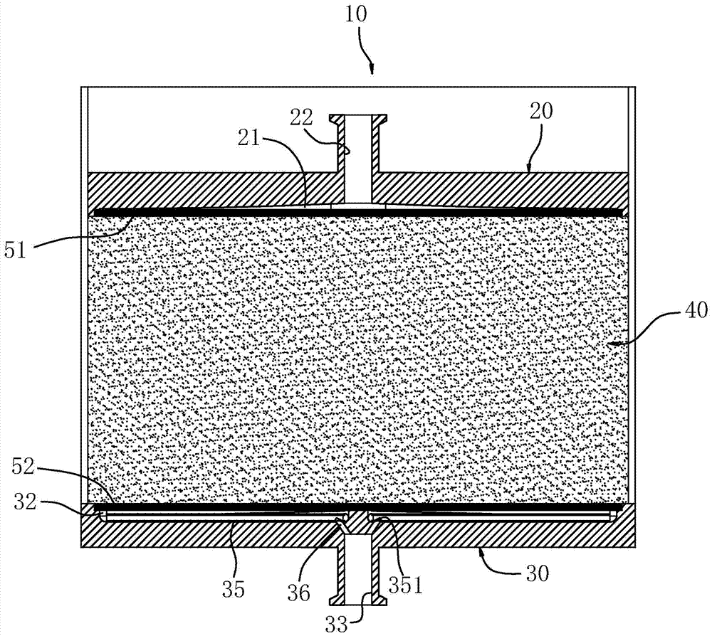
Figure 1 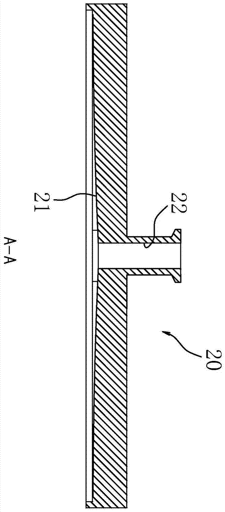
Figure 2 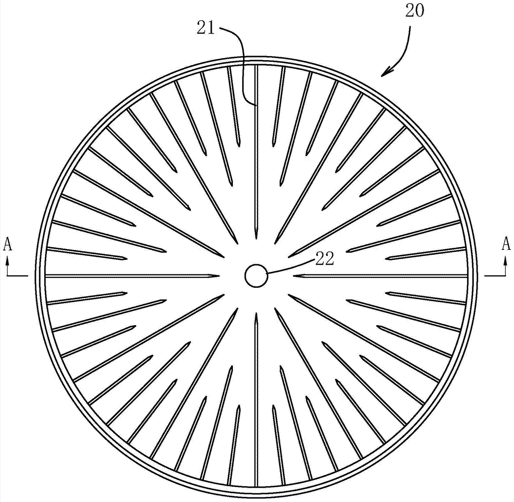
Figure 3
Abstract
Description
Technical field
[0001] The invention relates to a chromatographic column in gel chromatography technology, in particular to a pressure-coupled chromatographic column fluid distributor.
Background technique
[0002] Chromatography is a gel separation method, typically silica gel chromatography. It is separated by reacting the separation fluid with the gel in the chromatographic column through molecular sieve, ion exchange, etc. Chromatographic column is the main body of gel chromatography technology, generally using glass tube or plexiglass tube, which is filled with gel, and equipped with fluid distribution plate and sieve plate at both ends. Such as Figure 8 As shown, the traditional chromatographic column fluid distribution plate has a radial flow groove on one side, and a liquid inlet or outlet in the center. The fluid enters from the liquid inlet, flows through the radial flow groove to the edge of the fluid distribution plate, and then The gel flows out to the ed...
Examples
Embodiment Construction
[0018] The following examples are further explanations and illustrations of the present invention, and do not constitute any limitation to the present invention.
[0019] refer to figure 1 , the pressure-coupled chromatography column fluid distributor of the present invention includes a first distribution plate 20 and a second distribution plate 30 . The first distribution plate 20 and the second distribution plate 30 are respectively arranged at the two ends of the gel 40 in the chromatography column 10. The gel 40 can be a gel known in the art, which is used for different components in the liquid separation.
[0020] Such as figure 2 , image 3 As shown, the first distribution plate 20 is a disc-shaped body made of polypropylene plastic, and a plurality of radial first fluid grooves 21 are provided on the surface of the side opposite to the gel. In this embodiment, the first A fluid groove 21 is arranged on the lower side of the first distribution plate 20, and a plura...