
Injection pressure-boosting and speed-increasing structure of die casting machine
The technology of a die casting machine and a pressurized cavity is applied in the field of die casting machines, which can solve the problems of the quality of die castings, the high cost of magnesium alloy die casting machines, and the increase of production costs, and achieve the effects of full castings, simple and reasonable structure, and reliable performance.
Patent Information
- Authority / Receiving Office
- CN · China
- Patent Type
- Applications(China)
- Current Assignee / Owner
- Publication Date
- 2015-11-11
- Estimated Expiration
- Not applicable · inactive patent
Smart Images
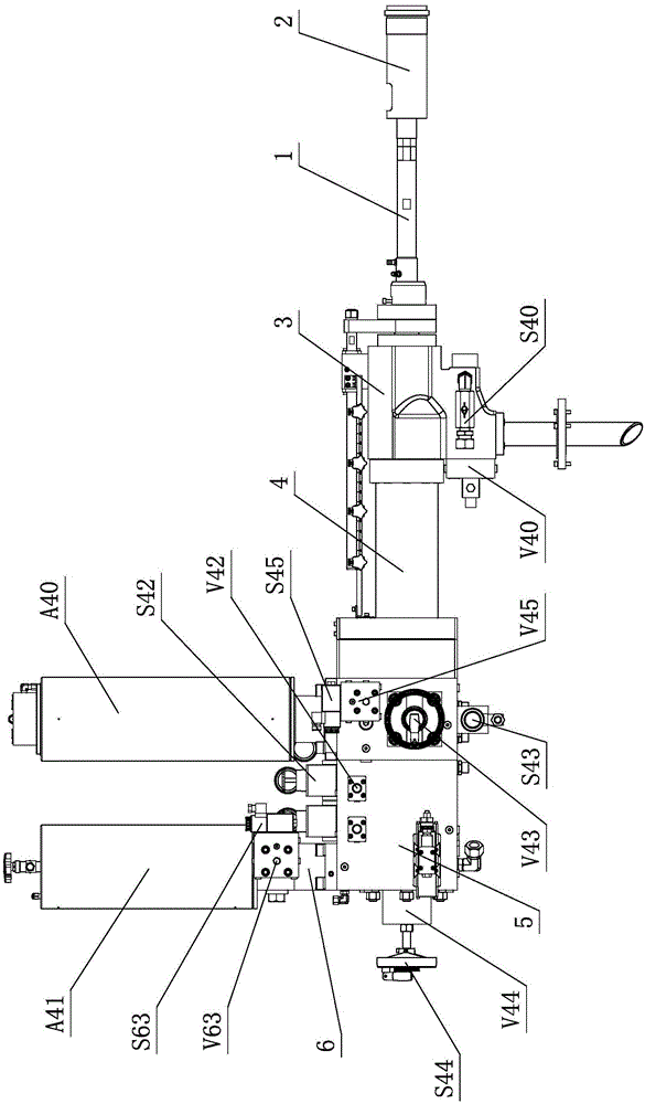
Figure 1 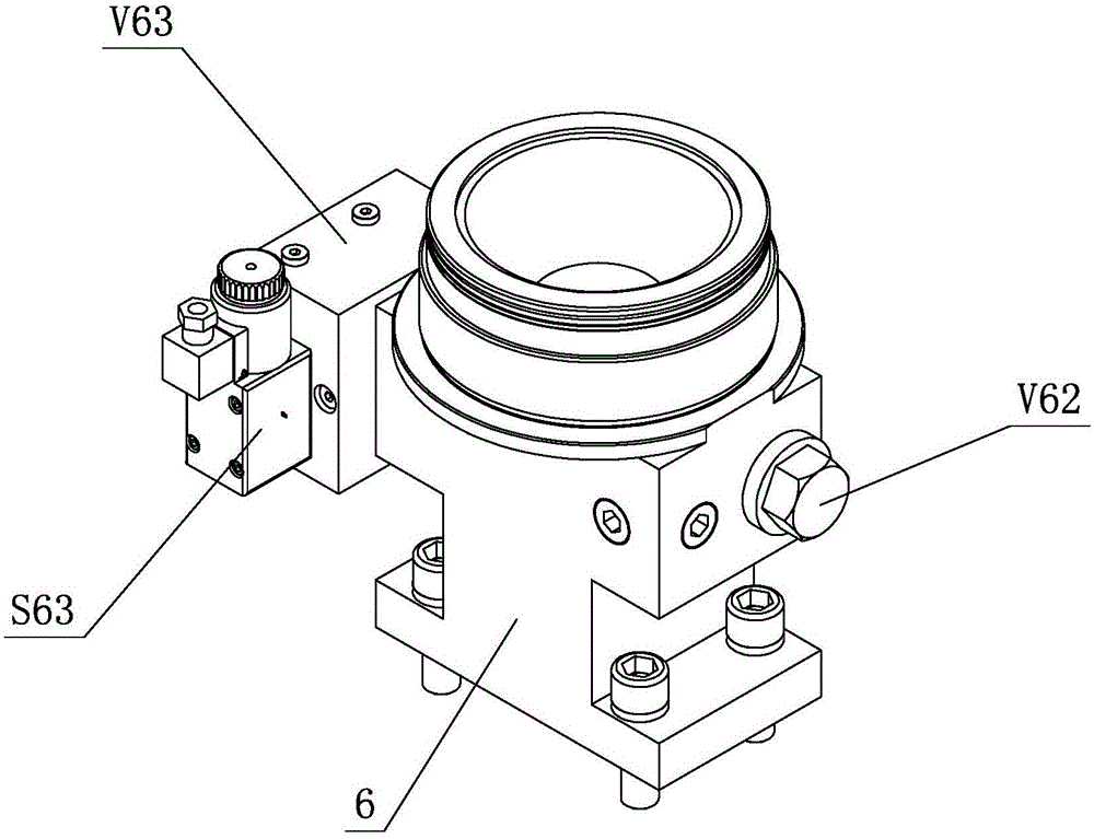
Figure 2 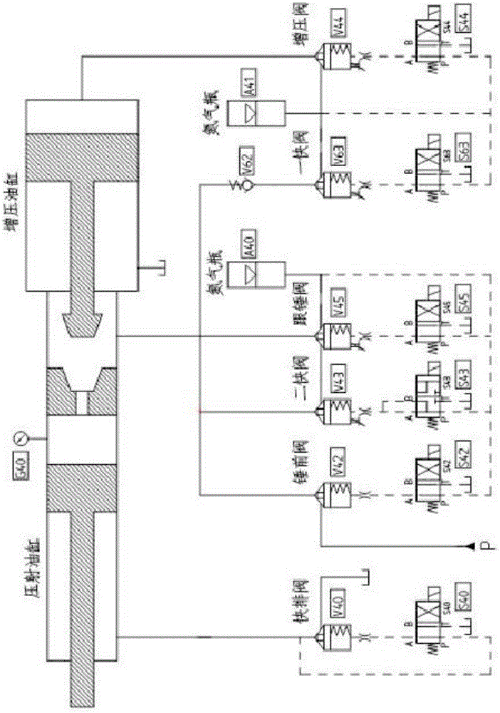
Figure 3
Abstract
Description
technical field
[0001] The invention relates to a die-casting machine, in particular to an injection pressurization speed-increasing structure of a die-casting machine. Background technique
[0002] Die-casting is the abbreviation of pressure casting. Its essence is to fill the die-casting mold cavity with liquid or semi-liquid metal at a high speed under the action of high pressure, and solidify under pressure to obtain castings.
[0003] Die casting is one of the most advanced metal forming methods. It is an effective way to achieve less chips and no chips. It is widely used and develops rapidly. The die-casting process is not only suitable for non-ferrous metals such as zinc, aluminum, magnesium and copper, but also for die-casting iron and steel castings. The size of the castings can range from a few millimeters to 1-2 meters, and the weight can range from a few grams to tens of kilograms. Die-casting Components are no longer limited to the automobile industry and the i...
Examples
Embodiment Construction
[0019] The present invention will be further described below in conjunction with the accompanying drawings and embodiments.
[0020] see figure 1 , figure 2 , the injection pressurization and speed-up structure of the die-casting machine includes an injection punch 1, one side of the injection punch 1 is provided with an injection part 2, and the other side of the injection punch 1 is sequentially provided with an injection cylinder 3 , the injection piston rod 4 and the booster cylinder 5, a booster chamber is formed between the injection piston rod 4 and the booster cylinder 5; the booster cylinder 5 is provided with a fast oil block assembly and two fast oil block assemblies components.
[0021] A fast oil circuit block assembly includes a fast oil circuit seat 6, a fast valve V63, a fast pilot valve S63 and a one-way valve V62; The cavities communicate with each other, and a fast valve V63, a fast pilot valve S63 and a one-way valve V62 are respectively arranged on a f...