
Ultraviolet discharge lamp
A discharge lamp and ultraviolet technology, applied in the direction of discharge lamps, gas discharge lamps, parts of gas discharge lamps, etc., can solve the problems of output energy attenuation, reduce the service life of ultraviolet discharge lamps, change the output spectrum, etc., to reduce the size, Improve working life and stability, increase the effect of breakdown voltage
Patent Information
- Authority / Receiving Office
- CN · China
- Current Assignee / Owner
- Publication Date
- 2016-03-23
Smart Images
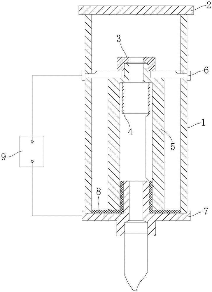
Figure 1 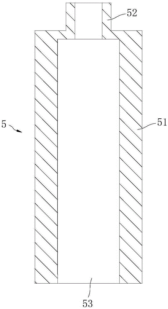
Figure 2 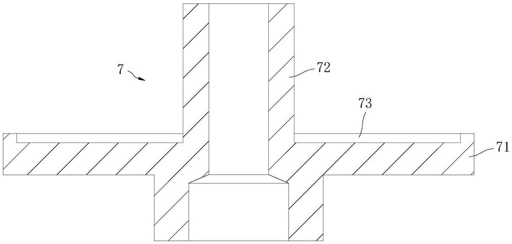
Figure 3
Abstract
Description
technical field
[0001] The invention relates to the technical field of gas analysis and detection instruments, and more specifically relates to an ultraviolet discharge lamp. Background technique
[0002] In the prior art, an ultraviolet discharge lamp usually includes a sealed cylindrical glass lamp tube filled with a low-pressure inert gas or an inert gas mixture. One end of the glass tube is hermetically bonded to a transparent output window for vacuum ultraviolet (VUV) transmission. One of the electrodes (negative electrode) is arranged inside the glass lamp tube, the other electrode (positive electrode) is arranged outside the glass lamp tube, and the two electrodes are respectively connected to the power supply. Under the excitation of an external electric field, the inert gas in the lamp tube undergoes glow discharge to generate vacuum ultraviolet rays, which are transmitted through the output window. The disadvantage of this ultraviolet discharge lamp is that when ...
Examples
Embodiment Construction
[0022] In order to have a clearer understanding of the technical features, purposes and effects of the present invention, the specific implementation manners of the present invention will now be described in detail with reference to the accompanying drawings.
[0023] Such as figure 1 , figure 2 , image 3 as well as Figure 4 As shown, one of the preferred embodiments of the present invention provides an ultraviolet discharge lamp, which includes a lamp tube 1, an output window 2, a first electrode 3, a second electrode 4, a ceramic tube 5, a first electrode holder 6, a second Two electrode holders 7 , an insulating structure 8 and a power source 9 .
[0024] Specifically, such as figure 1 As shown, the lamp tube 1 is a hollow cylindrical structure made of glass. The lamp tube 1 is filled with an inert gas or an inert gas mixture. In this embodiment, the lamp tube 1 is filled with krypton-helium or xenon-helium mixture at a pressure of 30-40 mmHg. Both ends of the lam...