
Direct Instantaneous Torque and Direct Levitation Force Control Method for Bearingless Switched Reluctance Motor
A switched reluctance motor, instantaneous torque technology, applied in motor generator control, AC motor control, electronic commutation motor control, etc. The effect of reducing torque ripple, stable rotation and suspension, and fast dynamic response
Patent Information
- Authority / Receiving Office
- CN · China
- Patent Type
- Patents(China)
- Current Assignee / Owner
- Publication Date
- 2019-01-29
Smart Images
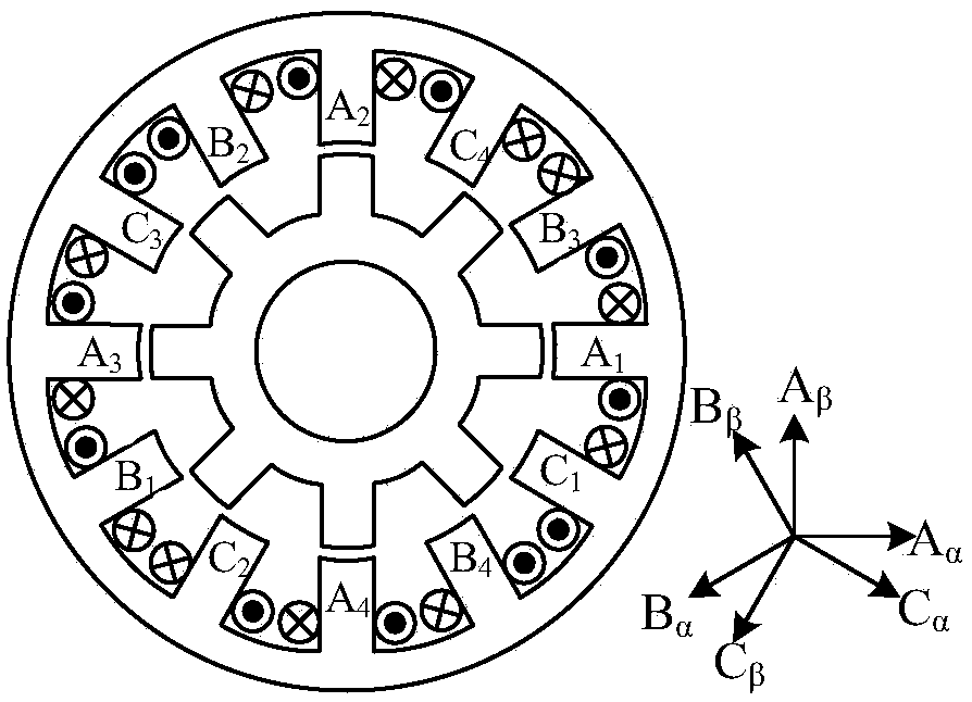
Figure 1 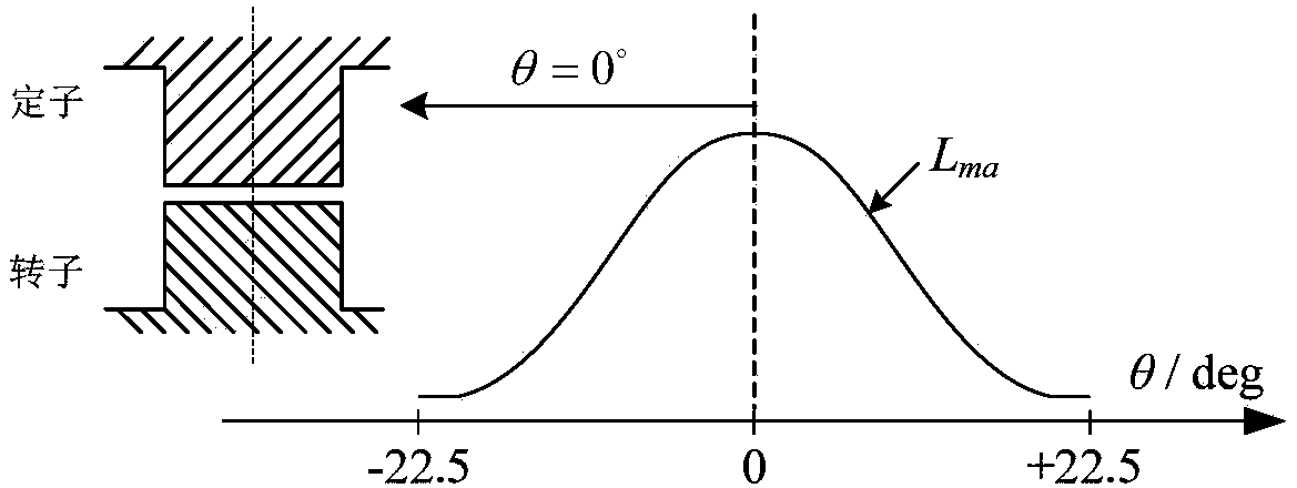
Figure 2 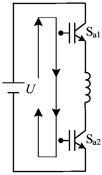
Figure 3
Abstract
Description
technical field
[0001] The invention discloses a direct instantaneous torque and direct suspension force control method of a bearingless switched reluctance motor, belonging to the technical field of switched reluctance motor control. Background technique
[0002] Switched reluctance motor has the characteristics of simple structure, reliable operation, low cost, high temperature resistance, high fault tolerance and high speed adaptability, etc., and has been widely used in aerospace, military, civil and other fields. A Bearinless Switched Reluctance Motor (BSRM for short), which integrates the functions of a magnetic bearing and a motor, realizes levitation operation while greatly reducing its volume and weight and increasing its power density. Due to the dual functions of rotation and suspension, the high-speed adaptability of BSRM is further improved, and it has better application advantages in aerospace and military fields.
[0003] For the traditional 12 / 8-pole single-...
Examples
Embodiment Construction
[0034] The technical solution of the invention will be described in detail below in conjunction with the accompanying drawings.
[0035] The present invention is aimed at 12 / 8 pole BSRM (such as figure 1 ), and according to the definition methods adopted in domestic and foreign literature, the zero degree of the rotor position angle is defined at the coincidence of the stator and rotor tooth pole axes, and the winding inductance value is the largest at this time (such as figure 2 shown).
[0036] Figure 3 shows three working states of the winding power circuit. In Figure 3(a), two power switches are turned on at the same time, and a positive voltage is applied to both ends of the winding, and the switching state is recorded as a "+" state; in Figure 3(b), only one switch is turned on, and the winding current enters a constant value In the freewheeling state, no voltage is applied to the winding, which is recorded as the "0" state; in Figure 3(c), the two power switch tubes ...