
multifunctional electric wine decanter
A decanter, multi-functional technology, applied in the field of wine, can solve problems such as single function
Patent Information
- Authority / Receiving Office
- CN · China
- Patent Type
- Patents(China)
- Current Assignee / Owner
- Publication Date
- 2018-07-17
Smart Images
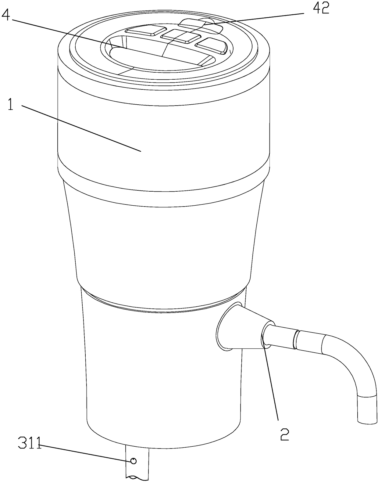
Figure 1 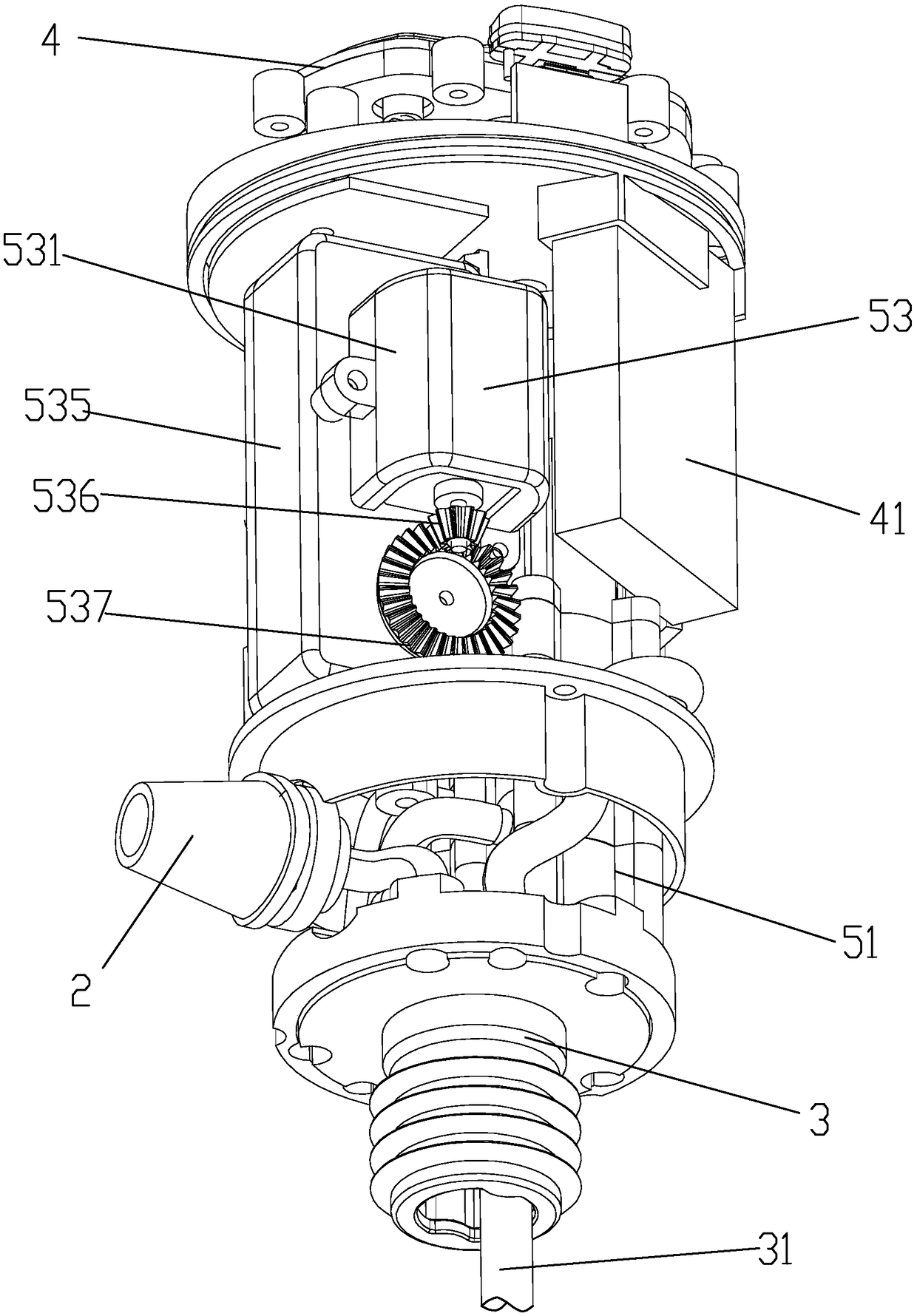
Figure 2 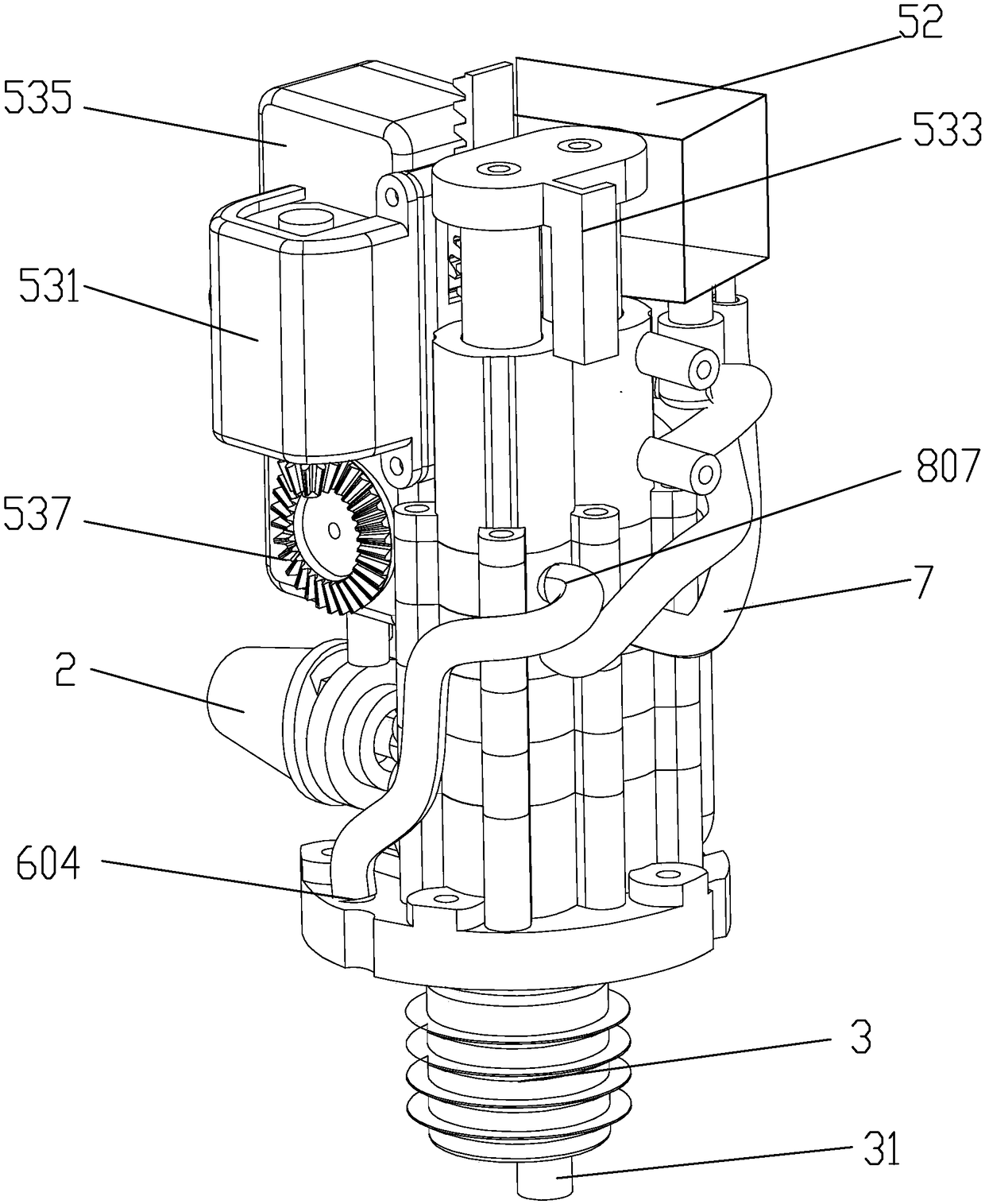
Figure 3
Abstract
Description
technical field
[0001] The invention relates to the technical field of wine, in particular to a wine decanter. Background technique
[0002] Wine must be sobered up to breathe to get a better taste. Sobered wine, after the wine is in full contact with the air, can soften the bitter tannins in the wine, so as to remove the miscellaneous flavors produced by long-term storage and make the wine The aroma of wine spreads. The traditional decanter is generally a glass vessel. In order to maximize the contact area between the red wine and the air, the bottom of the decanter is designed to be wider and the bottle mouth is smaller, but it still takes more than an hour to achieve the effect of sobering up. This kind of sobering device is too large in size, fragile, very inconvenient to carry or transport, and the effect of sobering up is slow, requiring a lot of waiting time to have a better sobering up effect.
[0003] And the application number is that CN201510409229.5 discloses "...
Examples
Embodiment Construction
[0034] Such as Figure 1-8 The multifunctional electric wine decanter shown includes a housing 1, a wine outlet pipe 2 located outside the housing 1, a fixed base 3 located at the bottom of the housing 1, and a control device 4 arranged on the housing 1, and the fixed base 3 There is a wine guiding tube 31 and a ventilation hole 32 for communicating with the air in the bottle. A ventilation system 5 is provided inside the shell 1. The ventilation system 5 has three working states: maintaining pressure, vacuuming, and sobering up wine. 5 includes a ventilation valve 51, an air pump 52 and a driving device 53, the ventilation valve 51 includes a valve body 8, a cylindrical left valve cavity 81 and a right valve cavity 82 are arranged in the valve body 8, and a cylindrical valve cavity 81 is provided in the left valve cavity 81. The left plunger rod 83 with sliding fit, the right plunger rod 84 with slip fit is arranged in the right valve cavity 82, and the left and right plunger...