
Anti-abrasion piston enchased ring
A technology of inserting rings and pistons, applied in the directions of pistons, engine components, machines/engines, etc., can solve the problem of high cost of use, and achieve the effect of improving tensile strength and flexural strength
Patent Information
- Authority / Receiving Office
- CN · China
- Patent Type
- Applications(China)
- Current Assignee / Owner
- Publication Date
- 2017-01-04
- Estimated Expiration
- Not applicable · inactive patent
Smart Images
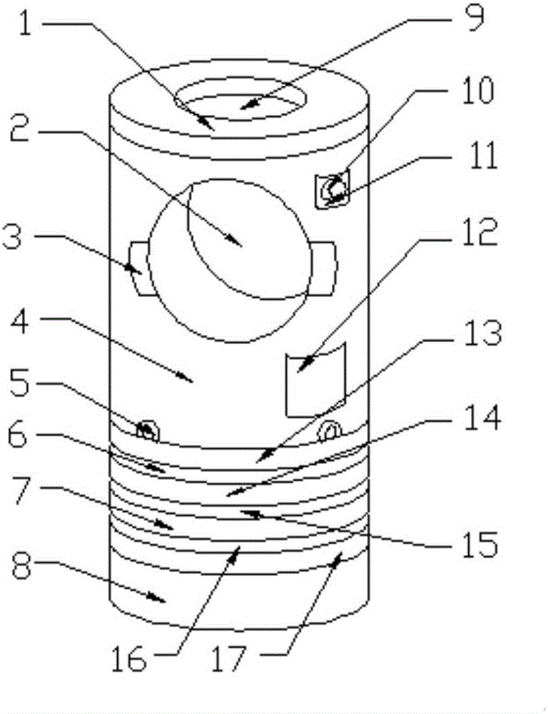
Figure 1 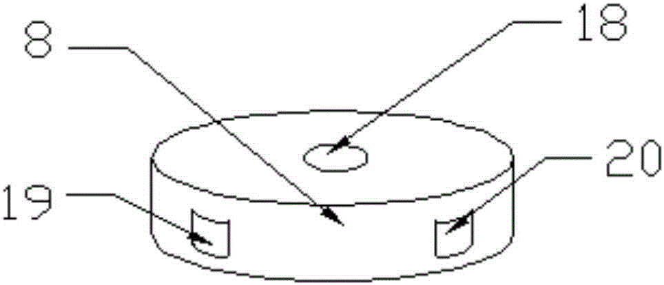
Figure 2
Abstract
Description
technical field
[0001] The invention relates to the technical field of insert rings, in particular to a wear-resistant piston insert ring. Background technique
[0002] The so-called piston ring, of course, refers to the movement of the piston in the cylinder. In a reciprocating piston internal combustion engine, the heat energy generated by fuel combustion pushes the piston back and forth in the cylinder, which becomes mechanical energy and is directly used by people. The working conditions of the piston in the cylinder are very harsh and harsh. First of all, it is a moving part. The piston needs to move back and forth in a straight line in the cylinder, and also needs to swing left and right slightly. Take a diesel engine with a rotating speed of 3000r / min as an example, the average speed of the piston in the cylinder is 10m / s, and the movement is alternating at the same time. At the upper and lower dead centers, the instantaneous speed of the piston is zero, and at a ce...
Examples
Embodiment Construction
[0014] The following will clearly and completely describe the technical solutions in the embodiments of the present invention with reference to the accompanying drawings in the embodiments of the present invention. Obviously, the described embodiments are only some, not all, embodiments of the present invention. Based on the embodiments of the present invention, all other embodiments obtained by persons of ordinary skill in the art without making creative efforts belong to the protection scope of the present invention.
[0015] see Figure 1-2 , the present invention provides a technical solution: a wear-resistant piston insert, including an insert main body 4, a positioning boss 1 is provided on the top of the insert main body 4, and a through hole is provided inside the positioning boss 1 9. The inside of the insert body 1 is provided with a positioning groove 2, the side of the positioning groove 2 is provided with a decorative block 3, and the side of the insert body 4 is ...