
Power rush-repair method using cable wiring device with balance device
A technology of emergency repair and balancing device for electric power, applied in the direction of overhead line/cable equipment, etc., can solve the problems of high labor intensity, long operation time, low efficiency, etc., and achieve the effect of improving overhead efficiency and extending the laying distance
Patent Information
- Authority / Receiving Office
- CN · China
- Patent Type
- Applications(China)
- Current Assignee / Owner
- Publication Date
- 2017-02-01
- Estimated Expiration
- Not applicable · inactive patent
Smart Images
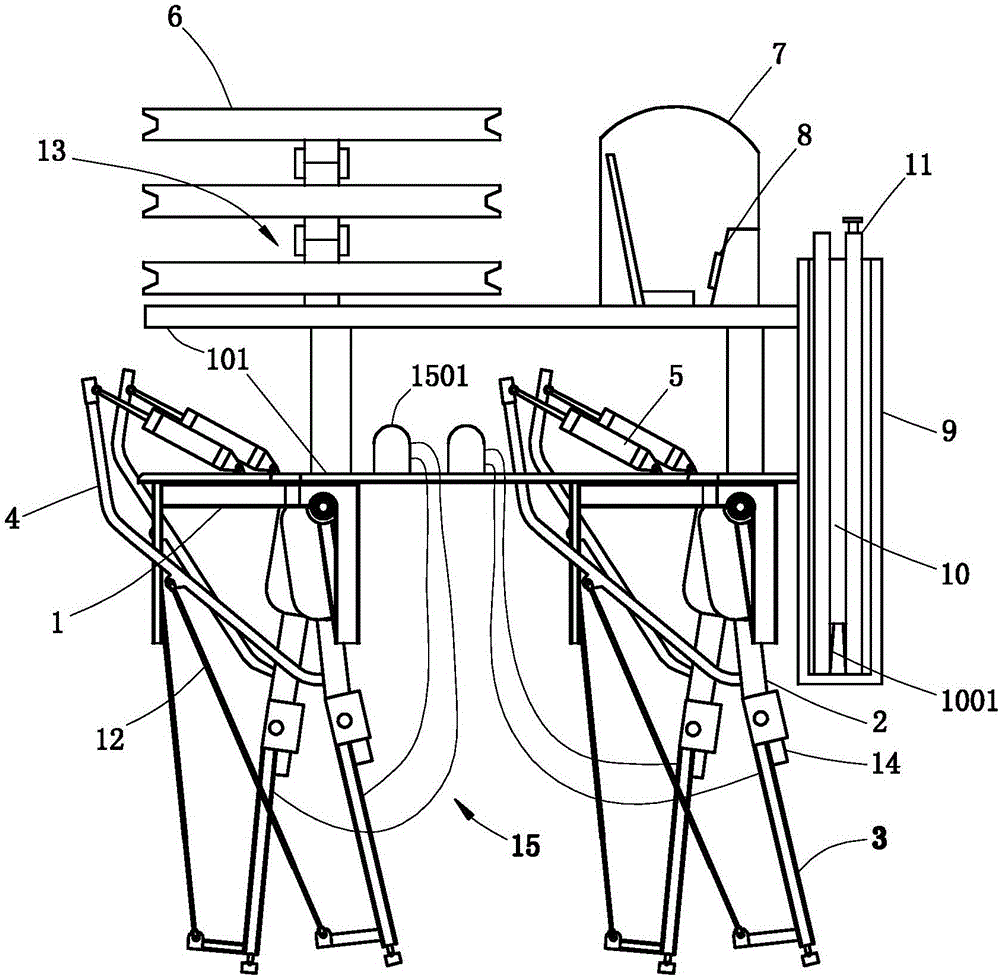
Figure 1 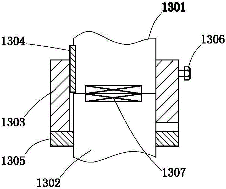
Figure 2 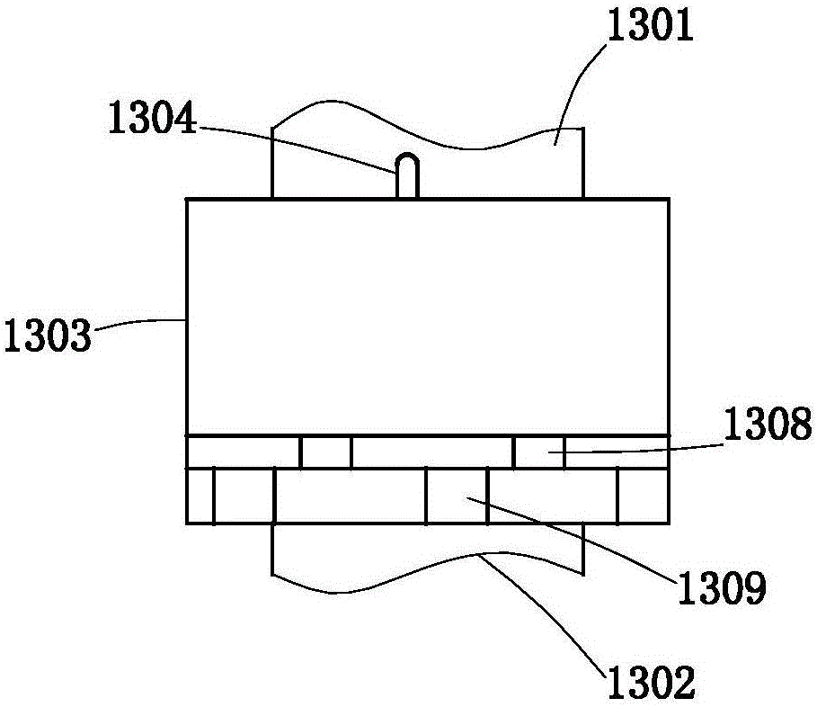
Figure 3
Abstract
Description
technical field
[0001] The invention relates to an electric power emergency repair method, in particular to an electric electric emergency repair method using a cable stringing device with a balancing device, and belongs to the technical field of electric power maintenance. Background technique
[0002] In modern industrialized society, people's life, work, and business operations are closely related to electricity all the time. Once a power failure occurs, it will bring great inconvenience to people's life and the normal operation of society. Especially when natural disasters such as storms, snowstorms, and earthquakes (such as the large-scale power interruption caused by the large-scale freezing on the eve of the Spring Festival in my country in 2009) will destroy the power supply, which will not only endanger people's normal life and industrial production, but also affect rescue work. It caused great inconvenience and delayed the rescue time.
[0003] How to quickly repai...
Examples
Embodiment Construction
[0047] Below in conjunction with the accompanying drawings, the present invention will be described in detail through specific embodiments, but the use and purpose of these exemplary embodiments are only used to illustrate the present invention, and do not constitute any form of any limitation on the actual protection scope of the present invention, let alone The protection scope of the present invention is limited thereto.
[0048] Such as figure 1 , figure 2 and image 3 Commonly shown, the present invention discloses a method of electric power emergency repair using a cable stringing device with a balance device, wherein the cable stringing device includes a frame 1, and the frame 1 is provided with a horizontally arranged operating platform 101, The front and rear ends of the console 101 are hingedly mounted with two opposite upper swing arms 2, each upper swing arm 2 is hingedly mounted with a lower swing arm, each upper swing arm 2 is connected to a drive arm 4, and t...