
Novel rotary spraying stirrer for preventing oil sludge deposition of crude oil storage tank
A crude oil storage tank and rotary jet technology is applied in the field of devices used for preventing sludge deposition in crude oil storage tanks, which can solve the problems of accelerated rotation speed, large fluid energy loss, low transmission efficiency, etc., and achieves stable speed control, easy processing and manufacturing, The effect of small energy loss
Patent Information
- Authority / Receiving Office
- CN · China
- Patent Type
- Applications(China)
- Current Assignee / Owner
- Publication Date
- 2017-10-13
- Estimated Expiration
- Not applicable · inactive patent
Smart Images
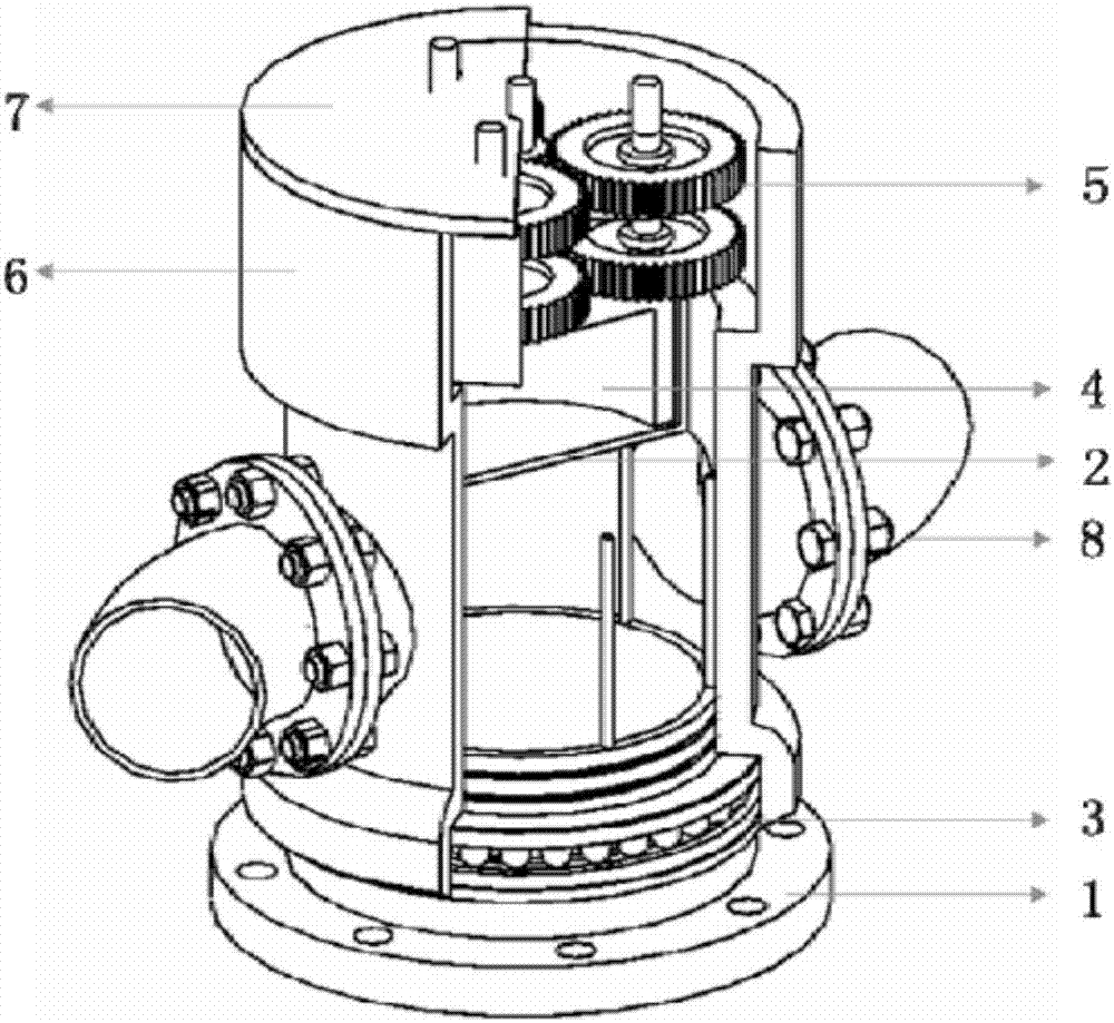
Figure 1 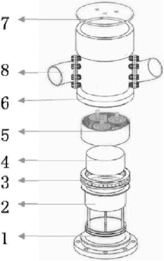
Figure 2 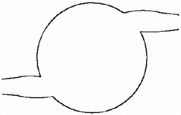
Figure 3
Abstract
Description
technical field
[0001] The invention relates to a device for preventing oil sludge deposition in crude oil storage tanks, in particular to a novel rotary jet agitator for preventing oil sludge deposition in crude oil storage tanks. Background technique
[0002] With the continuous development of the world economy, oil consumption has increased sharply. At the same time, with the advancement of the construction of strategic oil reserves in various countries, the number and capacity of crude oil storage tanks will increase day by day. During the storage of crude oil, oil phase stratification will occur due to the difference in density, resulting in different properties such as acid value and viscosity of crude oil in each layer in the storage tank, which is not conducive to the proportioning of crude oil and affects the stable operation of downstream refining units On the other hand, asphaltene, colloid, wax, etc. in crude oil are easy to aggregate and deposit to the bottom of...
Examples
specific Embodiment approach
[0019] The novel rotary jet agitator used for preventing oil sludge deposition in crude oil storage tank of the present invention, its preferred specific embodiment is:
[0020] Including the fixed base, the outer cylinder of the hydraulic damper, the thrust bearing, the inner cylinder of the hydraulic damper, the planetary gear mechanism, the rotating shell, the top cover, and the nozzle;
[0021] The outer cylinder of the hydraulic damper and the inner cylinder of the hydraulic damper together form a hydraulic damper, the lower end of the hydraulic damper is connected to the fixed base, and the input shaft at the upper end is connected to the output shaft of the planetary gear mechanism;
[0022] The fixed base is connected with the outer cylinder of the hydraulic damper through supporting ribs;
[0023] The nozzle is connected to the rotating shell through a flange, and the nozzle is an arc-shaped curved nozzle arranged concentrically or a straight nozzle arranged eccentric...
specific Embodiment
[0032] Such as Figure 1a to Figure 5b As shown, the rotary jet agitator and the storage tank, oil pipeline, valves and oil pumps form a rotary jet agitator system.
[0033] The oil pump pumps the crude oil from the bottom of the storage tank and transports it through the oil pipeline to the bottom inlet of the rotary ejector installed on the inner wall of the storage tank or at the center of the storage tank. The rotary jet agitator and the oil pipeline are connected by an 8-inch standard flange. If necessary, a reinforcing rib is set between the oil pipeline and the ground at the connection between the two to prevent the rotary jet agitator from shaking when it is working. The structure of the rotary jet agitator mainly includes a fixed base 1, a hydraulic damper outer cylinder 2, a thrust bearing 3, a hydraulic damper inner cylinder 4, a planetary gear mechanism 5, a rotating housing 6, a top cover 7, and a nozzle 8; The fixed base 1, the bottom of the hydraulic damper out...