
Grid automatic voltage control method and system based on multi-objective optimization
A multi-objective optimization and automatic voltage technology, applied in AC network voltage adjustment, circuit devices, AC network circuits, etc., can solve the multi-objective optimization without considering the number of switching equipment actions, the optimization target only considers a single, does not consider multiple Target optimization and other issues
Patent Information
- Authority / Receiving Office
- CN · China
- Patent Type
- Applications(China)
- Current Assignee / Owner
- Publication Date
- 2018-04-20
Smart Images
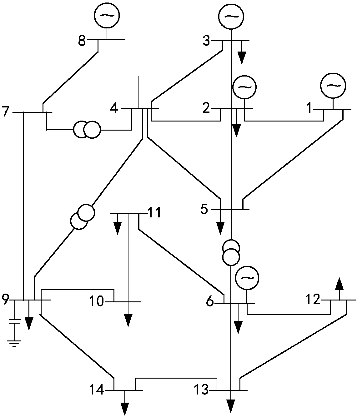
Figure 1 
Figure 2 
Figure 3
Abstract
Description
technical field
[0001] The present invention relates to the grid automatic voltage control (AVC) technology of the power system, in particular to a grid automatic voltage control method and system based on multi-objective optimization, which is used for coordinating discrete and continuous reactive resources and reducing the number of actions of grid switching equipment , reduce network loss and other optimization control objectives. Background technique
[0002] The Automatic Voltage Control (AVC) system is the main system of voltage and reactive power control in modern power grids. Through the automatic regulation of reactive power resources in the power grid, it can improve the voltage quality of the power grid, reduce network losses, and ensure safe, economical and high-quality operation of the power grid. The reactive power and voltage resources of the modern power grid include various grid-connected units on the power supply side, dynamic reactive power compensation eq...
Examples
Embodiment Construction
[0041] The following will be figure 1 The typical grid-IEEE-14 node standard system model shown is taken as an example to further describe in detail the grid automatic voltage control method and system based on multi-objective optimization in the present invention.
[0042] see figure 1 , where node 1 is connected to the upper-level power grid and is a balanced node, all nodes are P and Q nodes, and the upper and lower limits (per unit value) of the voltage amplitude of each node are 1.1 and 0.9 respectively, and nodes 2 and 14 are grid-connected For the unit, node No. 5 has dynamic reactive power compensation equipment, nodes No. 3, No. 6, and No. 8 have parallel capacitor banks, and all transformers are no-load tap-changing transformers. The grid model parameters and initial state (0 time) are shown in Table 1. As shown, the resistance, reactance, susceptance, voltage amplitude, active power, and reactive power data are all per unit values, the voltage phase angle is the am...