
Tar ammonia water clarifying tank and tar ammonia water clarifying system
A technology of ammonia water and storage tanks, which is applied in the field of coal chemical industry, can solve the problems that the liquid level inside the container cannot be observed, the leakage of the tank body cannot be detected in time, and the separation is not complete, etc., and it achieves small footprint, convenient layout and design, and convenient The effect of observation
Patent Information
- Authority / Receiving Office
- CN · China
- Patent Type
- Applications(China)
- Current Assignee / Owner
- Publication Date
- 2018-10-19
Smart Images
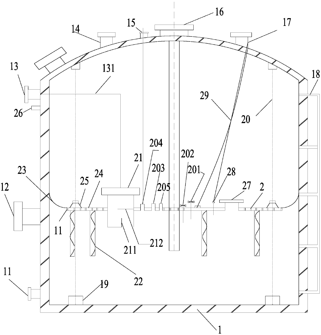
Figure 1 
Figure 2
Abstract
Description
technical field
[0001] The invention belongs to the field of coal chemical industry, and in particular relates to a tar ammonia water clarification storage tank and a tar ammonia water clarification system. Background technique
[0002] At present, the widely used ammonia water clarification and separation equipment mainly includes horizontal tar ammonia water clarification tank and vertical tar ammonia water separator. The commonly used tar ammonia water separation process includes mechanized tar ammonia water clarification tank process, mechanical scraping tank + vertical separation tank process and pre-separator + squeeze pump + vertical separation tank process. Among them, the horizontal tar ammonia clarifier is the most widely used.
[0003] Disadvantages of mechanized clarification tank: poor sealing, large floor area, many consumables, inconvenient cleaning of tar slag accumulation, and inability to detect and deal with the leakage of the tank in time, because of its...
Examples
Embodiment Construction
[0027] The present invention will be further described below in conjunction with the accompanying drawings and specific embodiments.
[0028] Such as figure 1 As shown, a tar ammonia water clarification storage tank of the present invention comprises a tank body 1 provided with a liquid inlet 16 at the top and an inner floating plate 2 arranged in the tank body 1, the liquid inlet 16 is connected to one end of the liquid inlet pipe, and The other end of the liquid pipe passes through the inner floating plate 2 and extends into the bottom of the tank body 1, and the edge of the inner floating plate 2 is provided with a sealing device 23 that is sealed with the inner wall of the tank body 1; Port 13, the liquid outlet 13 communicates with the solution pouring port 21 provided on the inner floating plate 2 through the flexible pipe 131, and one end of the solution pouring port 21 stretches into the bottom of the inner floating plate 2, and the tank body below the liquid outlet 13...