
Metal workpiece punching machine with positioning device
A technology for metal workpieces and positioning devices, applied in metal processing equipment, manufacturing tools, portable drilling rigs, etc., can solve the problems of lack of tools for processing small workpieces, large volume of machining tools, and inability to move conveniently. The effect of wide processing range and strong practicability
Patent Information
- Authority / Receiving Office
- CN · China
- Patent Type
- Applications(China)
- Current Assignee / Owner
- Publication Date
- 2018-10-26
- Estimated Expiration
- Not applicable · inactive patent
Smart Images
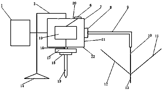
Figure 1 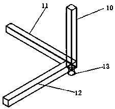
Figure 2
Abstract
Description
Technical field:
[0001] The invention relates to the field of metal workpiece processing devices, in particular to a metal workpiece punching machine with a positioning device. Background technique:
[0002] With the continuous development of science and technology, the productivity of the manufacturing industry has been greatly improved. The existing machining tools are various and large in size. Generally, they can only be used in a fixed position and cannot be moved conveniently. Existing drilling machine tools such as lathes and drilling machines are generally bulky and lack workpiece positioning devices, which are more suitable for mass production and processing of large workpieces, and lack tools suitable for processing small workpieces. Invention content:
[0003] The object of the present invention is to provide a metal workpiece punching machine with a positioning device, which solves one or more of the above-mentioned problems in the prior art.
[0004] In order...
Examples
Embodiment Construction
[0015] In order to deepen the understanding of the present invention, the present invention will be further described below in conjunction with the embodiments and accompanying drawings. The embodiments are only used to explain the present invention and do not constitute a limitation to the protection scope of the present invention.
[0016] Such as figure 1 As shown, it mainly includes a coordinate value input device 1, a support frame 3, a charging interface 6, a motor box 7, a coordinate receiver 8, a coordinate bar 9, a Z-axis rod 10, an X-axis rod 11, a Y-axis rod 12, and a positioning base point 13. Support base 14, motor 15, lead rod 16, shaft chassis 17, drill bit mounting frame 18, drill bit 19, top surface 20, side surface 21 and bottom surface 22, motor box 7 includes top surface 20, side surface 21 and bottom surface 22. The coordinate value input device 1 is electrically connected to the motor box 7. One end of the support frame 3 is installed at the center of the...