
Projection equipment
A technology of projection equipment and mounting boards, which is applied in optics, instruments, projection devices, etc., can solve the problems affecting the size of the lens, the size of the lens, and the limited work requirements of optical-mechanical components, so as to reduce resonance and noise and increase structural rigidity. Effect
Patent Information
- Authority / Receiving Office
- CN · China
- Current Assignee / Owner
- Publication Date
- 2019-04-02
- Estimated Expiration
- Not applicable · inactive patent
Smart Images
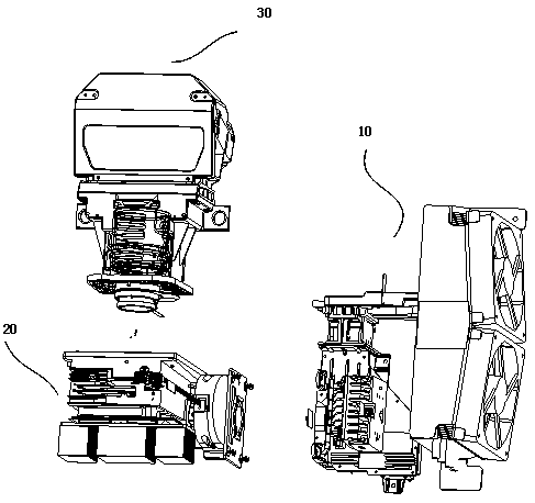
Figure 1 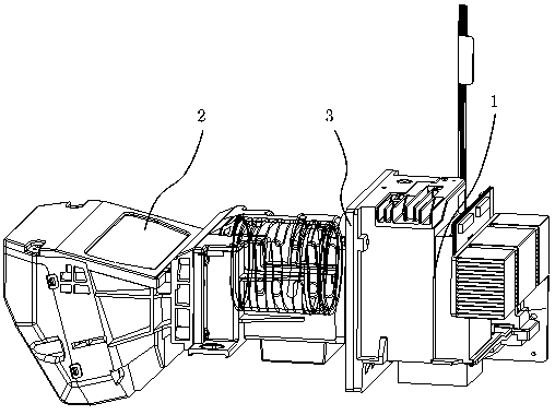
Figure 2 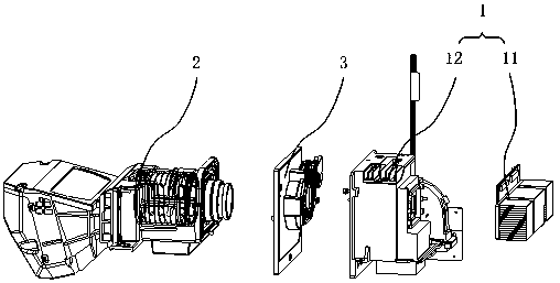
Figure 3
Abstract
Description
technical field
[0001] The present invention relates to the field of projection equipment, in particular to a projection equipment. Background technique
[0002] With the continuous development of science and technology, projection devices have been more and more widely used due to their advantages of large screen size and good visual effects.
[0003] figure 1 A schematic structural diagram of a projection device in the prior art is shown, such as figure 1 As shown, the projection device includes a light source module 10 , an optical machine module 20 , and a projection lens 30 . With the improvement of brightness requirements, the light source module 10 generally includes a laser component, such as a blue laser, or a blue laser and a red laser, or three-color lasers. The light source module 10 is where the heat source of the projection device is located, and is usually equipped with air-cooled or liquid-cooled heat dissipation devices. The light beam emitted by the lig...
Examples
Embodiment Construction
[0020] In order to make the purpose, technical solutions and advantages of the embodiments of the present invention clearer, the technical solutions in the embodiments of the present invention will be clearly and completely described below in conjunction with the drawings in the embodiments of the present invention. Obviously, the described embodiments It is a part of embodiments of the present invention, but not all embodiments. Based on the embodiments of the present invention, all other embodiments obtained by persons of ordinary skill in the art without creative efforts fall within the protection scope of the present invention.
[0021] figure 2 It is a schematic structural diagram of the projection device provided by Embodiment 1 of the present invention. image 3 yes figure 2 An exploded schematic of the projection device in . Figure 4 It is a schematic structural diagram of the galvanometer assembly in the projection device provided by Embodiment 1 of the present ...