
Magnetic sucking climbing robot
A robot and magnetic adsorption technology, which is applied in the field of robots, can solve problems such as being unable to meet the requirements of metal wall climbing, and achieve the effects of ensuring stability and safety, simplifying the mechanical structure, and improving reliability
Patent Information
- Authority / Receiving Office
- CN · China
- Patent Type
- Applications(China)
- Current Assignee / Owner
- Publication Date
- 2019-04-12
Smart Images
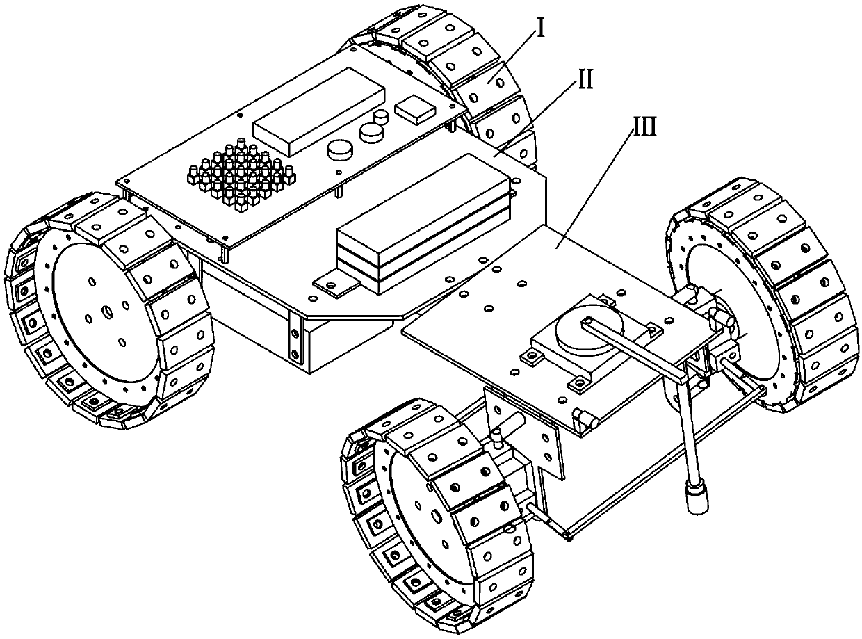
Figure 1 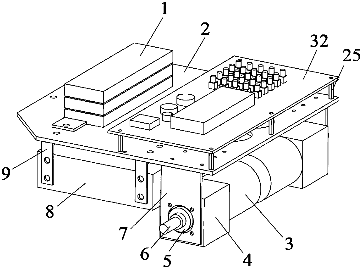
Figure 2 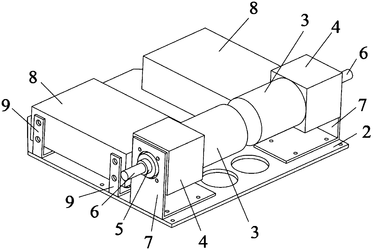
Figure 3
Abstract
Description
technical field
[0001] The invention belongs to the field of robots, and relates to a climbing robot, in particular to a magnetic adsorption climbing robot, which is a multifunctional machine detection platform capable of carrying a mechanical arm, high-definition image transmission equipment, and ultrasonic flaw detection equipment. Background technique
[0002] my country occupies an important position in the field of port cranes, and Shanghai Zhenhua represents a firm position in the world crane sector of Chinese companies. The monitoring and maintenance of cranes, especially large quay cranes, is becoming more and more important.
[0003] The non-destructive testing of metal equipment mainly includes X-ray non-destructive testing, electromagnetic ultrasound, ultrasonic, eddy current testing, magnetic flux leakage testing, penetrant testing, magnetic particle testing, etc. The testing equipment carried by the present invention is an ultrasonic non-destructive flaw detecto...
Examples
Embodiment Construction
[0035] The embodiments of the present invention are described in detail below. This embodiment is implemented on the premise of the technical solution of the present invention, and detailed implementation methods and specific operating procedures are provided, but the protection scope of the present invention is not limited to the following implementation example.
[0036] Such as figure 1 As shown, the robot of the present invention includes: a magnetic wheel I, a driving car body II, and a steering car body III.
[0037] Such as figure 2 As shown, the driving vehicle body II of the present invention includes: a vehicle body support structure, and a power drive device.
[0038] The vehicle body support structure includes a driving vehicle body main body 2 , a stepping motor driver bracket 9 and a stepping motor bracket 7 . The power drive device includes a stepper motor driver 8 , a stepper motor 3 , a stepper motor reducer 4 and an output shaft sleeve 5 . Such as image ...